
Introduction to MC Wiring and NEC Article 330
Metal-clad cable, universally recognized in the trade as MC wiring, is the backbone of modern commercial, industrial, and multi-family residential electrical distribution. prized for its physical protection, fire resistance, and ease of installation compared to rigid metal conduit (RMC) or electrical metallic tubing (EMT). However, the armored sheath that makes MC wiring so durable also introduces specific installation constraints that are strictly governed by the National Electrical Code (NEC).
For electricians, inspectors, and DIY enthusiasts tackling advanced projects, understanding NEC Article 330 is non-negotiable. This code explainer breaks down the critical standards for MC wiring, from bending radii and support spacing to environmental restrictions and termination protocols, ensuring your installation passes inspection and operates safely for decades.
Decoding the Armor: MC Wiring vs. AC Cable vs. Legacy BX
Before applying code rules, it is vital to correctly identify the cable type. The term 'BX' is often incorrectly used as a catch-all for all armored cable, but true BX is an obsolete, legacy product lacking a modern grounding path. Today, the NEC distinctly separates Type MC (Metal-Clad, Article 330) and Type AC (Armor-Clad, Article 320).
The Grounding Path Distinction
The primary difference lies in the equipment grounding conductor (EGC). Standard MC wiring contains a dedicated green insulated or bare copper grounding wire inside the armor. The metal sheath itself is not recognized as a primary grounding path under standard NEC rules. Conversely, Type AC cable relies on the combination of the metal armor and an internal aluminum bonding strip to serve as the EGC.
Furthermore, modern manufacturers produce MC-AP (Armor-Clad with Continuous Ground). In MC-AP wiring, the internal bare copper ground is in continuous physical contact with the metal armor, allowing the assembly to act as a redundant, high-fault-tolerant grounding path. Knowing which variant you are pulling from the spool dictates your termination and fitting requirements.
Critical NEC Bending Radius Requirements for MC Wiring
One of the most common reasons MC wiring fails a rough-in inspection is improper bending. Bending the cable too sharply can deform the corrugated or interlocked metal armor, which in turn can crush the internal THHN/THWN-2 conductors or compromise the paper/fiber separator, leading to short circuits or ground faults under load.
NEC Section 330.24 mandates strict minimum bending radii based on the physical construction of the cable sheath. The measurement is taken from the inner edge of the bend to the centerline of the cable.
| Cable Sheath Type | Minimum Bending Radius Multiplier | Example (for 0.5" Outer Diameter Cable) |
|---|---|---|
| Smooth Sheath MC | 10x the external diameter | 5.0 inches |
| Corrugated Sheath MC | 7x the external diameter | 3.5 inches |
| Interlocked Armor MC | 7x the external diameter | 3.5 inches |
Field Tip: When navigating tight 90-degree turns in commercial stud cavities, use manufactured MC bending springs or mechanical bending shoes to maintain the factory corrugation profile and prevent armor collapse.
Support and Securing: How Often Must MC Cable Be Fastened?
Because MC wiring is heavy and the interlocked armor can stretch or separate under its own weight over long vertical drops, NEC Section 330.30 enforces rigorous securing and supporting intervals. Unlike nonmetallic (NM/Romex) cable, which can sag without immediate mechanical failure, unsupported MC wiring can slowly pull apart at the fittings or stress the termination lugs inside junction boxes.
- Standard Intervals: MC wiring must be secured and supported at intervals not exceeding 6 feet (1.8 meters).
- Box Proximity: The cable must be secured within 12 inches (300 mm) of every box, cabinet, conduit body, or fitting where the cable terminates.
- Vertical Runs: For long vertical drops (such as down elevator shafts or multi-story chases), the cable must be supported at intervals not exceeding the limits specified in NEC Table 300.19(A) to prevent the internal conductors from bearing the weight of the entire vertical run.
Approved fastening methods include dedicated metallic or nonmetallic MC cable straps, clevis hangers, and cable ties listed for the specific application. Stapling MC wiring with standard nail-on Romex staples is a severe code violation and a guaranteed way to crush the armor.
Where MC Wiring is Prohibited: Environmental Restrictions
Despite its rugged metal exterior, standard MC wiring is not impervious to environmental degradation. NEC Section 330.12 explicitly outlines 'Uses Not Permitted.' Understanding these restrictions prevents catastrophic failure modes like hidden corrosion or insulation breakdown.
Corrosion and Wet Location Failures
Standard galvanized steel or aluminum MC wiring is strictly prohibited in the following environments unless it features a specific factory-applied corrosion-resistant jacket (such as a PVC outer shell):
- Direct Burial: Standard MC cannot be buried directly in earth or embedded in concrete. The alkaline nature of wet concrete and soil acids will rapidly eat through the interlocked armor.
- Wet Locations: Standard MC is rated for dry locations only. If installed outdoors, on a damp commercial rooftop, or inside a wash-down food processing facility, you must use Wet-Location MC, which features a continuous PVC jacket and wet-rated XHHW-2 internal conductors.
- Highly Corrosive Atmospheres: Areas with severe chemical fumes or continuous salt-spray exposure require specialized nonmetallic wiring or rigid PVC-coated conduit systems.
Proper Fitting and Termination Standards
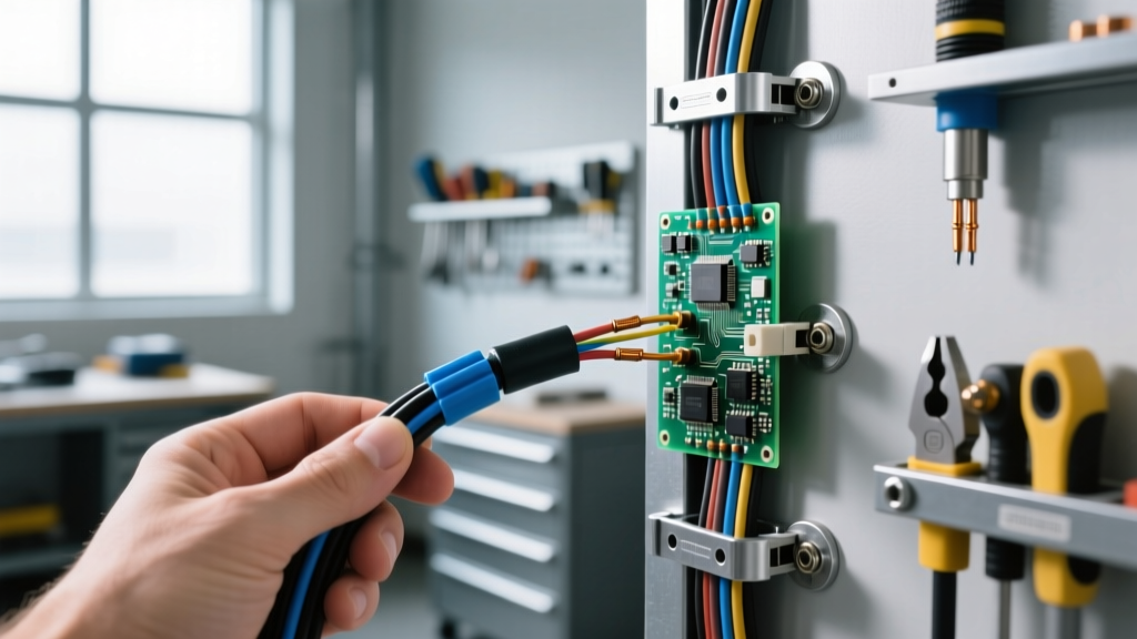
The transition point where MC wiring enters a steel junction box, panelboard, or device enclosure is the most vulnerable part of the system. The armor must be cleanly stripped without nicking the internal conductors, and the termination must protect the wires from the sharp, burred edges of the cut metal sheath.
While legacy AC cable strictly requires a red 'anti-short' bushing (often called a redhead) to prevent the bonding strip from shorting against the box, the NEC requirement for MC wiring is slightly different. NEC 330.12 requires that conductors be protected from abrasion. Because MC wiring features a dedicated internal ground wire and typically a robust internal binder tape, insulated throat fittings or listed MC connectors with built-in polymer sleeves are used to clamp the armor securely to the box while shielding the conductors. Always refer to the manufacturer's termination guidelines to ensure the specific connector is listed for use with the exact brand and type of MC cable being installed.
Real-World Failure Modes and Inspection Red Flags
Experienced electrical inspectors look for specific, recurring errors when evaluating MC wiring installations. Avoiding these common pitfalls will save you from costly rework:
- Over-Tightened Set Screws: Using a standard EMT setscrew connector on MC cable, or over-torquing a dedicated MC compression fitting, can crush the corrugated armor inward. This pinches the THHN insulation, creating a high-resistance ground fault that may not trip the breaker until the circuit is placed under heavy thermal load.
- Missing Box Clamps: Failing to use a listed MC connector and instead shoving the bare, cut end of the armor through a standard knockout. The sharp edges of the knockout will slice the conductor insulation the moment the wire is pulled or pushed during device installation.
- Improper Ground Pigtailing: In standard MC wiring, the metal armor cannot be used as the equipment ground. The internal green/bare wire must be pigtailed to the device ground screw and the metal box grounding pigtail. Relying on the armor alone for standard MC is a direct violation of NEC grounding principles.
Summary Checklist for Inspectors and Electricians
To ensure your MC wiring installation is fully compliant with NEC Article 330, run through this final checklist before calling for inspection:
- Verify the cable type matches the environment (Standard for dry, PVC-jacketed for wet/concrete).
- Confirm all bends meet the 7x or 10x diameter multiplier based on sheath type.
- Ensure straps and hangers are placed every 6 feet and within 12 inches of all boxes.
- Check that all cut ends utilize listed MC connectors that protect internal conductors from armor burrs.
- Verify the internal EGC is properly bonded to the box and device, independent of the metal sheath.
By treating MC wiring not just as a flexible conduit, but as a highly engineered, code-regulated assembly, you ensure the longevity, safety, and compliance of your electrical infrastructure.