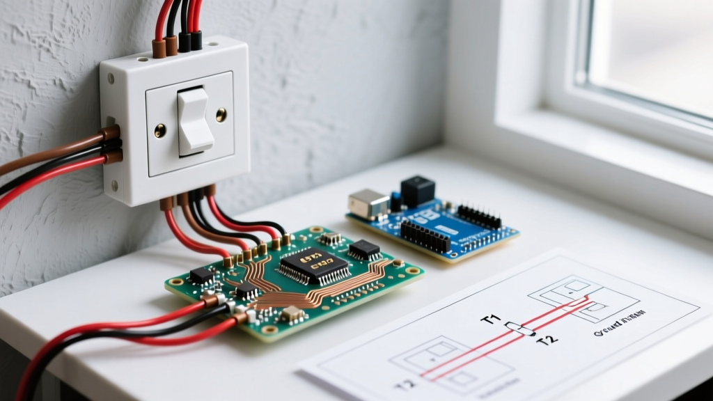

Why Your Three-Way Switch Circuit is Failing
Three-way switch circuits are notoriously frustrating to troubleshoot because they rely on a continuous, uninterrupted path through two separate switch locations and a pair of traveler wires. When a light fails to toggle correctly, the issue rarely stems from a defective switch; instead, it is almost always a misinterpretation of the diagram for wiring a three way switch. Whether you are working on a new construction rough-in or remodeling an older home, understanding how to read and verify your wiring diagram against real-world voltage is the only way to permanently solve the issue.
Before opening any junction box, safety is paramount. According to OSHA Electrical Safety Standards, you must verify the absence of voltage before touching any conductors. Use a reliable non-contact voltage tester like the Klein Tools NCVT-2 (approx. $30) and confirm the breaker is OFF at the panel. Never rely solely on the switch position to assume a circuit is dead.
Deconstructing the Standard Wiring Diagram
A standard mechanical three-way switch diagram consists of four critical electrical nodes. If your physical wiring does not map perfectly to these nodes, the circuit will fail.
- The Line (Power Source): The 120V AC hot wire (usually black) entering from the breaker panel. This must connect to the Common terminal (the dark-colored screw) on Switch 1.
- The Load (Light Fixture): The wire exiting the circuit to the light fixture. This must connect to the Common terminal on Switch 2.
- The Travelers: Two wires (often red and black, or two reds) that run between the brass-colored traveler screws on both switches. They carry the alternating current path depending on the toggle positions.
- The Neutral & Ground: The white neutral wire typically bypasses standard mechanical switches entirely, splicing directly through to the light fixture. The bare/green ground wires must be pigtailed to the green grounding screw on both switches and the metal box (if applicable).
Troubleshooting Matrix: Symptoms vs. Diagram Errors
Use this diagnostic matrix to quickly identify where your physical installation has deviated from your diagram for wiring a three way switch.
| Observed Symptom | Probable Diagram Misinterpretation | Corrective Action |
|---|---|---|
| Light only works from one switch location. | Line/Load wire is mistakenly landed on a brass traveler screw instead of the black common screw. | Move the hot/load wire to the dark common screw. Travelers must only connect to brass screws. |
| Breaker trips immediately upon resetting. | Neutral wire is incorrectly wired to a traveler terminal, or a ground is touching a hot traveler. | Remove neutral from the switch (unless using a smart switch). Ensure wire nuts are tight and no bare copper is exposed. |
| Switch works, but the light glows dimly when off. | Using a standard single-pole switch in a 3-way location, or ghost voltage from unshielded parallel wires. | Verify switch model (e.g., Leviton 5603). Ensure you are not using a dimmer not rated for 3-way LED loads. |
| Switch feels warm or emits a buzzing sound. | Backstabbed push-in connectors used instead of terminal screws, or 14 AWG wire on a 20A breaker. | Move wires to side-clamp terminal screws. Verify wire gauge matches breaker amperage (12 AWG for 20A). |
Top 3 Diagram Misinterpretations & How to Fix Them
1. The 'Common' Screw Swap
The most frequent error occurs when DIYers misidentify the common terminal. On a standard Leviton Decora 5603 three-way switch (approx. $4.50), the common screw is distinctly darker (black or dark bronze) and located on the opposite side of the two brass traveler screws. If you wire the incoming hot line to a brass screw, the circuit will only function when the other switch is in one specific position. Fix: Trace the Line and Load wires using a multimeter and ensure they terminate exclusively on the dark common screws of Switch 1 and Switch 2, respectively.
2. The Traveler Color Confusion
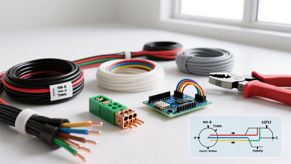
Standard diagrams show travelers as red and black. However, in remodel scenarios using 14/3 or 12/3 Romex, you will have a black, red, and white wire in the traveler bundle. The NEC requires that if the white wire is used as a hot traveler, it must be permanently re-identified with black or red electrical tape or heat-shrink tubing at both ends. Failing to do this confuses future electricians and violates code, leading to dangerous miswiring down the line.
3. Ignoring the Neutral Requirement for Smart Switches
If your diagram for wiring a three way switch involves smart home technology (like the Kasa HS210 or Lutron Caseta), the standard mechanical diagram is obsolete. Smart switches require a continuous 120V neutral wire at the switch box to power their internal Wi-Fi/radio relays. If your older home lacks a neutral in the switch box, you cannot use standard smart 3-way switches. Alternative: Use the Lutron Caseta PD-5S-DV system (approx. $65), which utilizes a wireless Pico remote for the second location, entirely eliminating the need for traveler wires and complex 3-way diagrams.
Step-by-Step Multimeter Diagnostic Flow
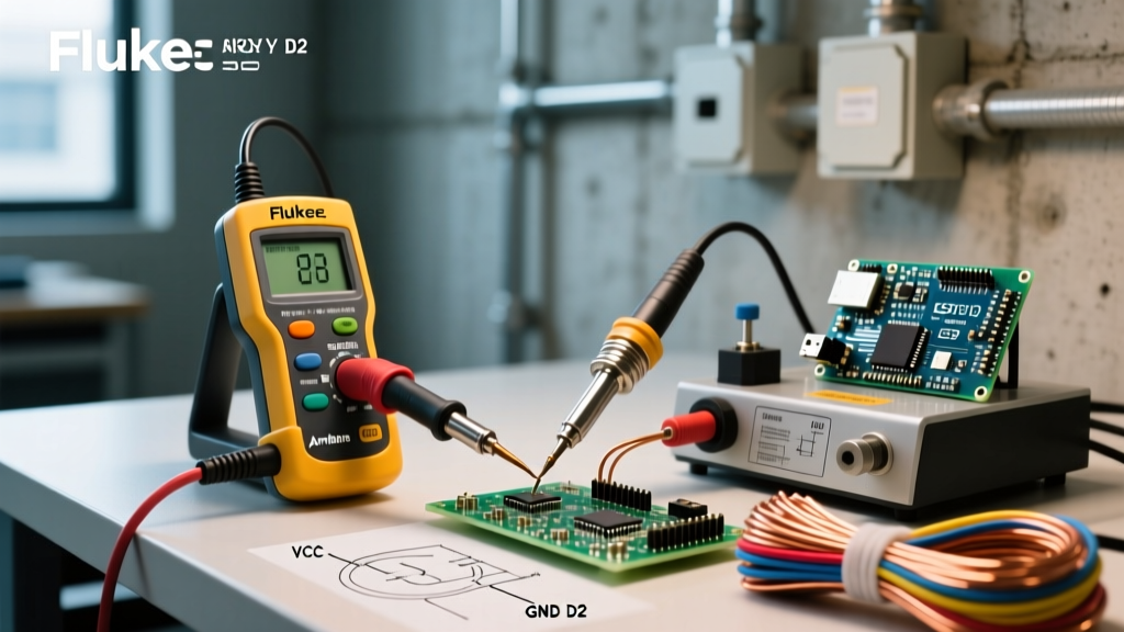
When visual inspection fails, use a True-RMS multimeter (like the Fluke 117, approx. $210) to test the circuit against your diagram. Follow this Fluke Continuity and Voltage Testing Guide methodology:
- Test Line Voltage (Power ON): With the breaker ON and switches disconnected, set the multimeter to AC Voltage (V~). Probe the suspected Line wire against the bare ground. A reading of ~120V confirms the Line wire. Mark it with black tape.
- Test Traveler Continuity (Power OFF): Turn the breaker OFF. Set the multimeter to Continuity (the diode/beep symbol). Connect one probe to a traveler wire at Switch 1 and the other to the travelers at Switch 2. You should get a beep (near 0 ohms) on exactly two wires. These are your confirmed travelers.
- Test Load Continuity: With power still OFF, probe the suspected Load wire against the neutral wire at the light fixture. A continuous beep confirms you have found the correct Load wire returning from the fixture.
NEC Code Compliance & Final Checks
When executing any wiring diagram, adherence to the National Electrical Code is non-negotiable. The NFPA National Electrical Code (NEC) Article 404.2(A) explicitly mandates that a neutral conductor must be provided at the switch location for all new construction and major remodels, even if you are currently installing a mechanical switch that does not require it. This ensures future-proofing for smart home upgrades.
Pro-Tip for 2026 Installations: Always use side-wiring terminal screws or screw-clamp plates rather than push-in 'backstab' connectors. Backstab connections rely on a tiny metal spring that can loosen over time due to thermal expansion and contraction, leading to high-resistance arcing and potential fire hazards, especially on 15A and 20A lighting circuits.
By methodically comparing your physical wires to the diagram for wiring a three way switch, verifying the common vs. traveler terminals, and utilizing a multimeter to eliminate guesswork, you can resolve even the most stubborn staircase lighting failures. Always cap unused wires, torque terminal screws to manufacturer specifications, and ensure your junction boxes are not overfilled beyond their cubic inch capacity ratings.