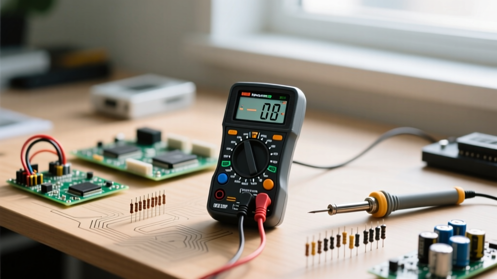

Stepping into the world of electronics, DIY wiring, or microcontroller programming requires more than just a soldering iron and a breadboard. You need a diagnostic window into the invisible flow of electrons. For anyone embarking on this journey, finding the right multimeter for beginners is the most critical first investment you will make. However, simply buying the tool is only step one; knowing how to progressively master its functions is what separates frustrated hobbyists from competent technicians.
This guide is structured as a Skill-Building Path. We will not just throw a manual at you. Instead, we will walk through five distinct stages of multimeter mastery—from selecting your first reliable unit to executing advanced component-level diagnostics and avoiding catastrophic safety blunders.
Stage 1: Selecting Your Foundation (The Hardware)
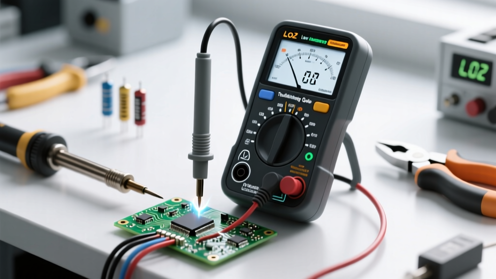
The biggest mistake novices make is purchasing a $10 no-name multimeter from an online marketplace. These cheap units often lack basic safety protections, feature sluggish auto-ranging, and use PVC probe leads that melt the moment they touch a soldering iron. When selecting a multimeter for beginners, you must prioritize safety ratings (CAT III), True RMS accuracy, and build quality.
The Entry-Level vs. Mid-Tier Comparison
Here is a decision framework based on real-world pricing and specifications to help you choose the right tool for your current skill level and budget.
| Model | Approx. Price | Counts / Display | Safety Rating | Best For |
|---|---|---|---|---|
| AstroAI DM6000AR | $35 | 6000 Counts | CAT III 600V | Absolute beginners, basic Arduino/battery testing |
| Kaiweets HT118A | $40 | 9999 Counts | CAT III 600V | Hobbyists needing True RMS and capacitance |
| Brymen BM235 | $95 | 6000 Counts | CAT III 600V | Serious makers, EE students, reliable daily driver |
Pro-Tip: Always upgrade to silicone probe leads immediately. Standard PVC leads will melt on your workbench and emit toxic fumes, whereas silicone withstands high heat and remains flexible in cold environments.
Stage 2: Mastering the 'Holy Trinity' of Basic Measurements
Before attempting to diagnose complex AC mains wiring or sensitive IoT circuits, you must build muscle memory with the three foundational measurements. According to SparkFun's multimeter tutorial, these three functions will solve 80% of your daily workbench problems.
1. Continuity (The Beep Test)
Continuity checks if two points are electrically connected. It is your primary tool for finding broken traces, verifying breadboard connections, and checking fuses.
- How to use: Turn the dial to the soundwave/diode symbol. Touch the probes together to verify the meter beeps.
- Skill Drill: Take a piece of stranded wire, strip both ends, and verify continuity. Then, intentionally nick the wire in the middle until it breaks internally, and use the meter to find the hidden break by bending the wire while probing.
2. DC Voltage (V⎓)
Used for batteries, USB power, and microcontroller logic levels (like the 5V or 3.3V pins on an Arduino or ESP32).
- How to use: Set the dial to DC Voltage. Place the red probe on the positive terminal and the black probe on the ground/negative terminal.
- Skill Drill: Measure a fresh 9V alkaline battery (should read ~9.4V), then measure it while it is connected to a small DC motor to observe 'voltage sag' under load.
3. Resistance (Ω)
Resistance measures how much a component opposes current flow. Crucial for verifying resistor values before soldering them into tight PCB spaces.
- Rule of Thumb: Never measure resistance on a live, powered circuit. The external voltage will confuse the meter's internal test current and can damage the multimeter.
Stage 3: Advancing to Component-Level Diagnostics
Once you are comfortable with basic voltage and continuity, it is time to unlock the intermediate features of your multimeter. This is where you transition from a 'wire checker' to a true electronics diagnostician.
The Diode Test Function
Standard resistance checks cannot accurately test semiconductor junctions. The diode test function pushes a small, specific current through the component and measures the forward voltage drop.
- Silicon Diodes (e.g., 1N4007): Should read between 0.5V and 0.7V in the forward direction, and 'OL' (Over Limit) in reverse.
- Schottky Diodes (e.g., 1N5819): Will read lower, typically 0.2V to 0.3V.
- LEDs: You can actually use this mode to faintly illuminate red or green LEDs while verifying their polarity (anode vs. cathode) before soldering.
Capacitance Testing
Measuring capacitance (in µF or nF) is vital when repairing power supplies or audio amplifiers. Warning: You must safely discharge large electrolytic capacitors using a high-wattage bleed resistor before measuring them. A charged capacitor can instantly destroy the capacitance measurement IC inside your multimeter.
Stage 4: The Danger Zone – Current Measurement & Safety Blunders
Measuring current (Amps) is fundamentally different from measuring voltage. While voltage is measured in parallel, current must be measured in series—meaning you must break the circuit and force the electricity to flow through the multimeter.
The 'Amps Jack' Catastrophe
The most common way beginners destroy their multimeters (and sometimes start a fire) is by leaving the red probe in the 10A Current Jack and then probing a voltage source, like a wall outlet or a battery.
Failure Mode Analysis: The 10A jack contains a very low-resistance shunt resistor (often less than 0.01Ω) designed to measure voltage drop caused by current. If you place this shunt directly across a voltage source, you create a dead short circuit. Massive current will instantly vaporize the shunt, melt the probe leads, and potentially cause the meter to explode if it lacks a proper HBC (High Breaking Capacity) ceramic fuse. Always double-check your probe placement before touching a live circuit.
For a comprehensive breakdown of safety categories and internal fuse mechanics, refer to the Fluke multimeter safety guide. Understanding CAT III and CAT IV ratings is non-negotiable if you plan to move from low-voltage DC electronics to AC mains troubleshooting.
Measuring Low-Power IoT Current (µA)
If you are designing battery-powered IoT sensors (like those using deep-sleep modes on ESP8266 chips), standard Amp ranges won't cut it. You must use the dedicated µA (micro-amp) jack. This circuit includes a higher resistance shunt to accurately measure currents in the 10µA to 400µA range, which is critical for calculating battery life expectancy.
Stage 5: Maintenance and Knowing When to Upgrade
A multimeter for beginners is a stepping stone. As your skills evolve, you will encounter signals that a standard digital multimeter (DMM) simply cannot visualize.
Probe Maintenance
Your probes are the physical interface with your work. Over time, the tips will accumulate oxidized solder and flux residue, leading to fluctuating resistance readings. Clean your probe tips regularly with isopropyl alcohol (IPA) and a brass sponge. If the nickel or gold plating wears off, replace the probes; do not attempt to sand them down, as this will ruin the precision tip geometry.
Graduating to Advanced Tools
While a DMM gives you the average or RMS value of a signal, it is blind to high-speed changes. You will know it is time to upgrade your toolkit when:
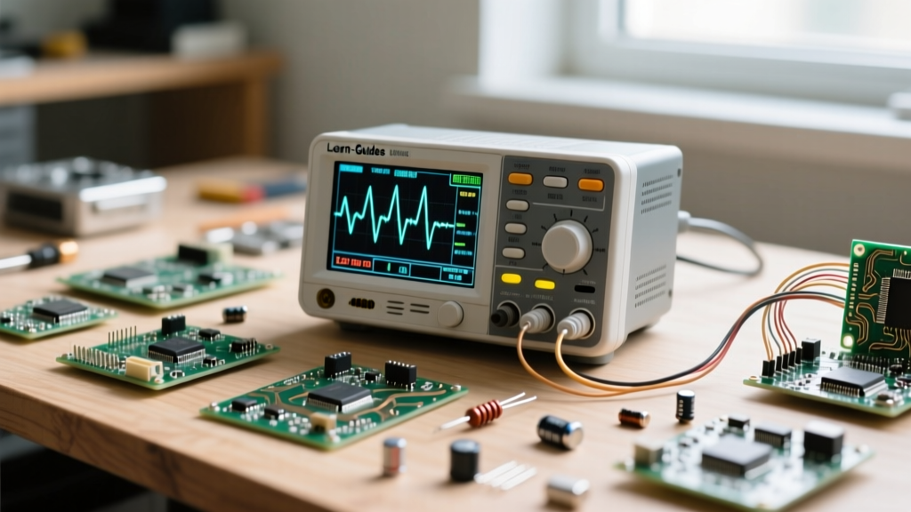
- You need to visualize AC ripple on a DC power supply line (Requires an Oscilloscope).
- You need to decode I2C, SPI, or UART data packets between microcontrollers (Requires a Logic Analyzer).
- You need to measure the Equivalent Series Resistance (ESR) of aging capacitors without desoldering them (Requires an ESR Meter).
By following this skill-building path, you ensure that your first multimeter serves as a reliable, safe, and educational partner on your workbench. For further reading on integrating digital multimeters into automated test environments, check out the National Instruments DMM documentation. Master the basics, respect the safety limits, and let the data guide your next build.