
The Anatomy of an I2C Mux Failure
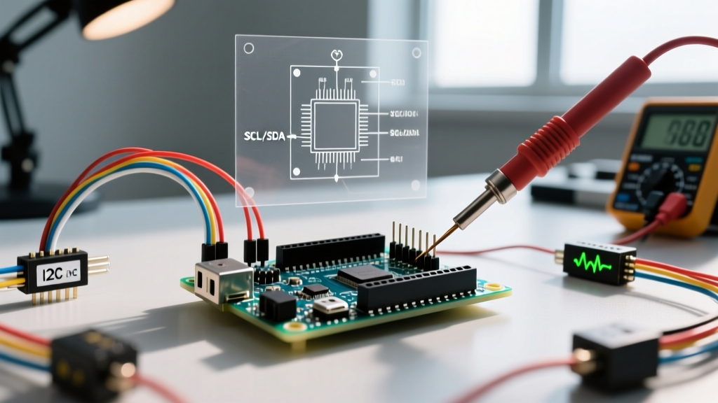
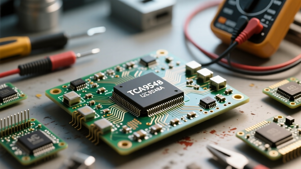
Integrating an I2C mux (multiplexer) like the Texas Instruments TCA9548A or NXP PCA9540B into your Arduino, ESP32, or Raspberry Pi project is the standard solution for resolving address conflicts. Whether you are wiring up four identical BME280 environmental sensors or a cluster of SSD1306 OLED displays, the mux acts as a traffic controller. However, treating an I2C mux as a simple digital switch is a fundamental misunderstanding that leads to hours of frustrating debugging.
Unlike a standard logic gate, the TCA9548A utilizes analog pass-gate FETs (Field Effect Transistors) to connect the upstream master bus to the downstream sub-buses. This means the downstream capacitance, pull-up resistor networks, and voltage levels interact directly with the master bus when a channel is active. When errors occur, they rarely manifest as simple 'device not found' messages. Instead, you will encounter complete microcontroller lockups, intermittent NACK (Not Acknowledged) errors, and ghost addresses. This guide provides a deep-dive diagnostic framework for isolating and resolving these hardware-level failures.
Symptom 1: Complete Bus Lockup and Scanner Blindness
The most catastrophic failure mode in an I2C mux circuit is a total bus lockup. When this happens, standard I2C scanner sketches freeze indefinitely, and the microcontroller's hardware watchdog may eventually trigger a reset. This is almost always caused by one of two physical layer issues.
The Floating Reset Pin Oversight
The TCA9548A features an active-low RESET pin. Many makers leave this pin floating if they do not need software-controlled resets. In electrically noisy environments—especially near switching power supplies or motor drivers—electromagnetic interference (EMI) can induce a voltage spike that the mux interprets as a reset signal. If the mux resets mid-transaction while a sub-bus is connected, the internal state machine desynchronizes from the master's I2C clock, effectively holding the SDA line low and locking the entire upstream bus.
The Fix: Never leave the RESET pin floating. If you are not controlling it via a GPIO pin, hardwire it directly to VCC or use a 10kΩ pull-up resistor to VCC to ensure a stable logic HIGH state.
Downstream SDA Contention and the 9-Clock Recovery
If a downstream sensor experiences a brownout or power glitch while transmitting a logic '0', it will continue to hold the SDA line low, waiting for clock pulses that the master has already stopped sending. Because the mux's pass-gate is open, this low state propagates directly to the master bus, freezing the Arduino.
The Fix: Implement a software bus-clearing routine before initializing your sensors. Temporarily reconfigure the master's SCL pin as a standard digital output and manually toggle it HIGH and LOW 9 times. According to the NXP I2C-bus specification (UM10204), 9 clock pulses are sufficient to force any stuck slave device to complete its byte transmission and release the SDA line, allowing the master to issue a proper STOP condition.
Symptom 2: Intermittent NACK Errors and Rise-Time Violations
If your I2C scanner occasionally detects devices but data reads fail with NACK errors or corrupted payloads, you are likely violating the I2C bus capacitance limits or miscalculating your pull-up resistors.
Pull-Up Resistor Miscalculations
The I2C specification mandates a maximum bus capacitance ($C_b$) of 400pF for standard and fast-mode operations. The TCA9548A adds approximately 10pF to 15pF of internal capacitance per channel. A common mistake is placing 4.7kΩ pull-up resistors on the master bus and on every single sub-bus breakout board. When the mux opens a channel, these resistors are placed in parallel, drastically lowering the total resistance. This causes the logic LOW voltage ($V_{OL}$) to rise above the acceptable threshold, resulting in NACK errors.
Use the following table to select the correct pull-up resistor values based on your estimated bus capacitance and desired clock speed:
| Total Bus Capacitance ($C_b$) | Pull-Up for 100kHz (Standard) | Pull-Up for 400kHz (Fast) |
|---|---|---|
| < 100pF | 10kΩ | 4.7kΩ |
| 100pF - 200pF | 4.7kΩ | 2.2kΩ |
| 200pF - 400pF | 2.2kΩ | 1.0kΩ |
| > 400pF | Requires I2C Bus Buffer (e.g., PCA9600) | |
Note: Always remove redundant pull-up resistors from downstream sensor modules if the master bus already has adequately sized pull-ups, or calculate the parallel equivalent resistance ($R_{eq}$) to ensure it stays above the minimum sink current threshold.
Symptom 3: The Logic Level Translation Myth
A pervasive myth in the maker community is that the TCA9548A acts as a bidirectional logic level shifter. It does not. The pass-gate FETs simply pass the voltage present on the master side to the sub-bus side. If your Arduino operates at 5V, the SCL and SDA lines on the active sub-bus will be pulled up to 5V.
Connecting a strictly 3.3V sensor (like a modern BME688 or SCD40) to a 5V-driven mux channel will result in one of two outcomes: the sensor's internal protection diodes will clamp the voltage, causing massive current draw and bus lockups, or the sensor's silicon will be permanently damaged. If your project requires mixing 5V masters with 3.3V sensors through a multiplexer, you must either use a mux with integrated level shifting (like the PCA9306 paired with a standard mux) or place dedicated MOSFET-based level shifters (like the BSS138 circuit) on the downstream lines.
Expert Diagnostic Insight: When debugging a complex mux tree, do not rely solely on the standard Arduino Wire.h library. Use a logic analyzer or an oscilloscope to inspect the SDA rise times. If the rise time from LOW to HIGH exceeds 1000ns (for 100kHz mode) or 300ns (for 400kHz mode), your pull-up resistors are too weak for the existing capacitance, regardless of what your software scanner reports.
Advanced Diagnostic Workflow
When your I2C mux circuit fails to initialize, follow this strict hardware-to-software diagnostic sequence to isolate the fault:
- Isolate the Master: Disconnect the mux entirely. Run an I2C scanner to verify the microcontroller's internal I2C peripheral and primary pull-ups are functioning correctly.
- Verify Mux Acknowledgement: Connect only the VCC, GND, SDA, and SCL lines to the TCA9548A (leave sub-buses empty). Scan for address
0x70. If it does not appear, check your wiring and ensure the A0, A1, and A2 address pins are tied to GND. - Channel-by-Channel Sweep: Send the control byte to enable Channel 0 (
0x01). Run the scanner. Repeat for Channels 1 through 7 (0x02through0x80). If a specific channel fails to acknowledge the master, the pass-gate FET for that channel may be damaged, or the downstream wiring has a short to ground. - Load Testing: Connect your sensors one by one. After adding each sensor, monitor the bus with a logic analyzer to ensure the voltage drop during a logic LOW ($V_{OL}$) remains below 0.4V. If it creeps higher, your pull-up network is too strong (resistance too low) for the combined sink current of the devices.
References and Further Reading
- NXP UM10204: I2C-bus specification and user manual - The definitive guide to I2C capacitance limits, rise-time requirements, and bus clearing procedures.
- Texas Instruments TCA9548A Product Page & Datasheet - Essential reading for understanding pass-gate FET resistance ($R_{on}$) and internal capacitance specifications.
- Adafruit TCA9548A I2C Multiplexer Learning Guide - Practical wiring diagrams and Arduino code examples for channel switching.