
The Hidden Complexities of the Mega Arduino Pinout
The Arduino Mega 2560 is the undisputed workhorse for complex DIY electronics, robotics, and 3D printer control boards. With its ATmega2560-16AU microcontroller offering 54 digital I/O pins and 16 analog inputs, it solves the I/O starvation common on the Uno. However, this massive expansion introduces severe pinout traps. A wiring scheme that works flawlessly on an Uno will often cause silent failures, bus collisions, or even permanent silicon damage on the Mega.
As of 2026, a genuine Arduino Mega 2560 Rev3 retails for around $28, while CH340-based clones hover near $14. Regardless of the board variant, the underlying ATmega2560 architecture dictates strict electrical rules. This troubleshooting guide dissects the most frequent Mega Arduino pinout errors, providing actionable fixes, exact measurements, and schematic-level insights to get your project back online.
Quick Reference: Critical Pin Alternate Functions
Before troubleshooting, you must understand that many digital pins on the Mega harbor hidden alternate functions tied to internal hardware timers and communication buses. Misallocating these causes peripheral conflicts.
| Function | Mega 2560 Pins | Common Uno Equivalent | Troubleshooting Note |
|---|---|---|---|
| PWM Output | 2-13, 44-46 (15 total) | 3, 5, 6, 9, 10, 11 | Pins 11, 12, 13 share Timer0/1/2. Using analogWrite() here may break delay() or Servo libraries. |
| External Interrupts | 2, 3, 18, 19, 20, 21 | 2, 3 | Interrupt mapping is non-sequential. Pin 20 is INT3, not INT4. |
| SPI Bus | 50 (MISO), 51 (MOSI), 52 (SCK), 53 (SS) | 11, 12, 13 | Using pins 11-13 for SPI on a Mega will fail silently. Always use the 50-53 block or the 6-pin ICSP header. |
| I2C Bus (Wire) | 20 (SDA), 21 (SCL) | A4 (SDA), A5 (SCL) | The classic Uno trap. A4/A5 on the Mega are strictly analog; they do not route to the TWI hardware. |
Troubleshooting Silent Digital I/O and PWM Failures
Symptom: Motor or LED on Pins 11, 12, or 13 is Unresponsive
On the Arduino Uno, pins 11, 12, and 13 are standard digital I/O and double as the SPI bus. On the Mega 2560, these pins are mapped to completely different internal ports (PORTB) and are heavily tied to Timer1 and Timer2. If you are porting code from an Uno and using the Servo library or analogWrite(), you may inadvertently overwrite the timer registers controlling these pins.
The Fix:
- Relocate PWM Signals: Move your PWM-driven components (like L298N motor driver ENA/ENB pins) to the dedicated Mega PWM cluster: pins 44, 45, and 46. These are driven by Timer3 and Timer5, isolating them from core system timers.
- Verify SPI Routing: If you are trying to drive an SPI display (like the ILI9341) and getting a blank screen, verify your wiring. The Mega SPI pins are 50 (MISO), 51 (MOSI), 52 (SCK), and 53 (SS). For maximum reliability, bypass the digital headers entirely and wire directly to the 2x3 ICSP header near the ATmega chip, which guarantees correct SPI routing across all Arduino form factors.
Resolving Analog Input Drift and Noise
Symptom: analogRead() Values Fluctuate Wildly on A0-A15
The Mega features 16 analog channels (A0-A15) multiplexed into a single 10-bit ADC. A common complaint is severe noise or 'ghosting' where reading A0 affects the value of A1.
Root Cause 1: Source Impedance Mismatch
The ATmega2560 datasheet specifies that the ADC sample-and-hold capacitor requires a source impedance of 10 kΩ or less to fully charge within the 1.5 ADC clock cycles allocated for sampling. If you are reading a high-impedance voltage divider (e.g., using 100kΩ and 100kΩ resistors for battery monitoring), the capacitor won't charge, resulting in ghost voltages from the previously polled pin.
- Fix: Lower your voltage divider resistor values to the 10kΩ/10kΩ range, or buffer the signal using an LM358 or MCP6001 op-amp configured as a unity-gain voltage follower.
Root Cause 2: Floating Analog Pins
Unconnected analog pins act as antennas, picking up 50/60Hz mains hum and injecting noise into the internal ADC multiplexer.
- Fix: Ground all unused analog pins via software by setting them to
INPUT_PULLUP, or physically tie them to GND via a 10kΩ resistor if hardware noise is severe.
Expert Tip: If your project demands high precision, bypass the noisy onboard 5V USB rail for analog references. Feed a clean 4.096V reference from an LM4040 or REF02 into the AREF pin, and change your sketch to analogReference(EXTERNAL). This dramatically shrinks the ADC step size, yielding vastly superior sensor resolution.
Communication Bus Collisions: The I2C Trap
Symptom: I2C Scanner Finds Zero Devices
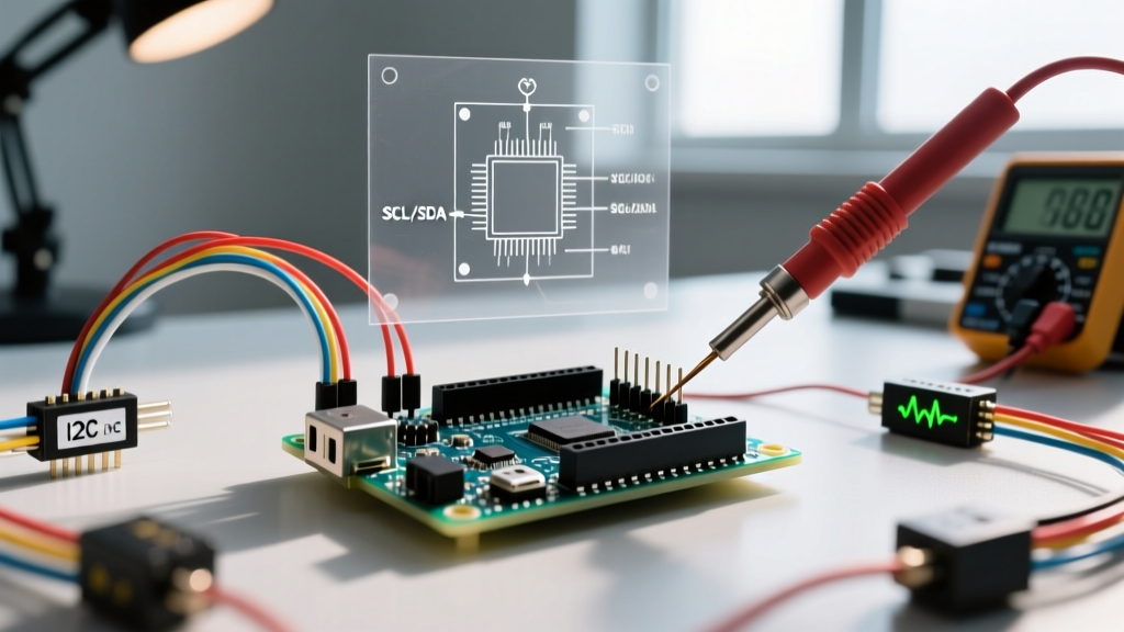
This is the single most common Mega Arduino pinout error. Makers wire their OLED displays, MPU6050s, or BME280 sensors to A4 and A5 out of pure muscle memory from the Uno. On the Mega, A4 and A5 are strictly analog inputs. The hardware TWI (Two-Wire Interface) bus is physically routed to Digital Pin 20 (SDA) and Digital Pin 21 (SCL).
The Fix:
- Rewire to the Correct Headers: Move your SDA/SCL lines to pins 20 and 21. Alternatively, use the dedicated 6-pin header located right next to the AREF pin, which duplicates the I2C bus and provides a convenient GND and 5V rail.
- Check Pull-Up Resistors: The Mega's internal pull-ups (enabled via
Wire.begin()) are roughly 30kΩ to 50kΩ. According to the NXP I2C Bus Specification, a 30kΩ pull-up is too weak for standard 400kHz Fast Mode communication, especially with the Mega's higher trace capacitance. If your devices fail to initialize, solder external 4.7kΩ pull-up resistors between the SDA/SCL lines and the 5V (or 3.3V) rail.
Power Rail Failures and Voltage Regulator Thermal Throttling
Symptom: The Mega Randomly Resets or the 5V Pin Outputs 4.2V Under Load
The Mega 2560 is often tasked with powering multiple sensors, relays, and LCD backlights directly from its 5V pin. This inevitably leads to power rail collapse.
Understanding the Mega Power Architecture:
- USB Polyfuse: The USB VBUS line is protected by a resettable PTC polyfuse (RXE050) that trips at 500mA. If your USB-connected peripherals draw more than this, the fuse heats up and disconnects the circuit.
- NCP1117 Voltage Regulator: When powered via the DC barrel jack or VIN pin, the board uses an NCP1117ST50T3G linear regulator. While rated for 1A on paper, the SOT-223 package on the PCB lacks a dedicated heatsink.
The Thermal Math:
If you supply 12V to the barrel jack and draw 300mA from the 5V pin, the regulator must dissipate the voltage difference as heat:
Power (W) = (Vin - Vout) * Current
Power = (12V - 5V) * 0.3A = 2.1 Watts
Without a heatsink, the NCP1117 will hit its thermal shutdown threshold (approx. 150°C) in seconds, dropping the 5V rail and resetting the ATmega2560.
Actionable Fixes:
- Lower the Input Voltage: If using the barrel jack, use a 7V to 7.5V regulated wall adapter instead of a 12V supply. This cuts the thermal dissipation in half, allowing safe continuous draws up to 500mA.
- Bypass the Onboard Regulator: For high-current projects (e.g., driving 5V WS2812B LED strips or multiple 5V servos), do not use the Mega's 5V pin. Instead, use an external buck converter (like an LM2596 module, costing under $3) to step your main supply down to 5V, and wire that directly to the Mega's 5V header pin, bypassing the NCP1117 entirely.
Diagnostic Flowchart for Dead Pins
When a specific pin on your Mega refuses to respond, follow this diagnostic sequence before declaring the ATmega2560 chip dead:
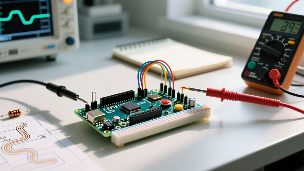
- Run the Blink Test: Write a basic sketch toggling the suspect pin HIGH and LOW every 500ms. Measure with a multimeter. If it toggles, the hardware is fine; your issue is a software library conflict.
- Check for Physical Shorts: Use a multimeter in continuity mode to check resistance between the suspect pin and GND. A reading below 10Ω indicates a blown trace or a shorted external component pulling the pin low.
- Inspect the Solder Joints: Clone boards manufactured with wave-soldering processes occasionally suffer from cold solder joints on the female headers. Reflow the header pins with a soldering iron set to 350°C using a touch of fresh 63/37 rosin-core flux.
Summary
Mastering the Mega Arduino pinout requires unlearning the physical constraints of the Uno. By respecting the dedicated SPI block (50-53), routing I2C strictly to 20/21, managing ADC source impedance, and treating the onboard linear regulator with thermal caution, you eliminate 95% of the hardware gremlins that plague complex MCU projects. For deeper architectural details, always refer to the Arduino Official Mega 2560 Documentation and the Microchip ATmega2560 Datasheet.