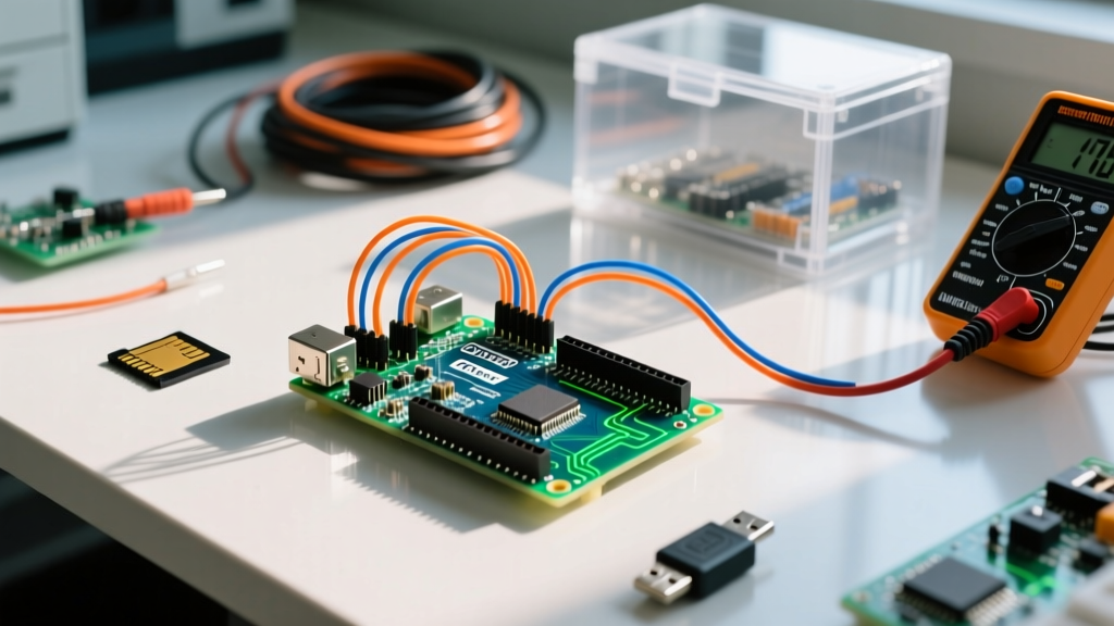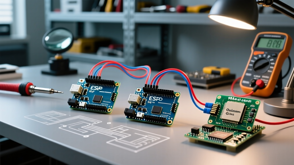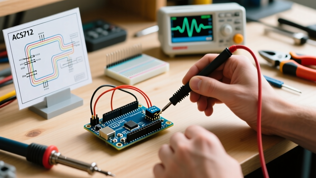

When scaling an Arduino project from a single proof-of-concept sensor to a multi-node environmental monitoring array, developers inevitably hit a silicon wall: I2C address collisions. You want to use four BME280 environmental sensors, but they all share the same hardcoded I2C address. You want to deploy six MPU6050 IMUs, but desoldering microscopic pull-up resistors and cutting PCB traces to change addresses destroys your development momentum. This is where implementing i2c multiplexing transitions from a niche hardware trick to an essential workflow optimization strategy.
By integrating an I2C multiplexer (MUX) into your prototyping and production workflows, you eliminate hardware rework, modularize your C++ architecture, and drastically reduce debugging time. This guide explores how to leverage i2c multiplexing to streamline your MCU development process, focusing on electrical best practices, software abstraction, and advanced bus debugging.
The Hardware Bottleneck: Address Collisions and Rework
In a standard maker workflow, encountering an address collision usually triggers a frustrating hardware hack. Take the ubiquitous GY-521 (MPU6050) breakout board. It has an AD0 pin that allows you to shift the address from 0x68 to 0x69. That gives you exactly two sensors on a single bus. If your project requires four IMUs for motion tracking, you are forced to either bit-bang software I2C on random GPIO pins (which consumes CPU cycles and lacks hardware interrupt support) or physically modify the breakout boards.
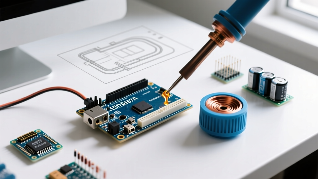
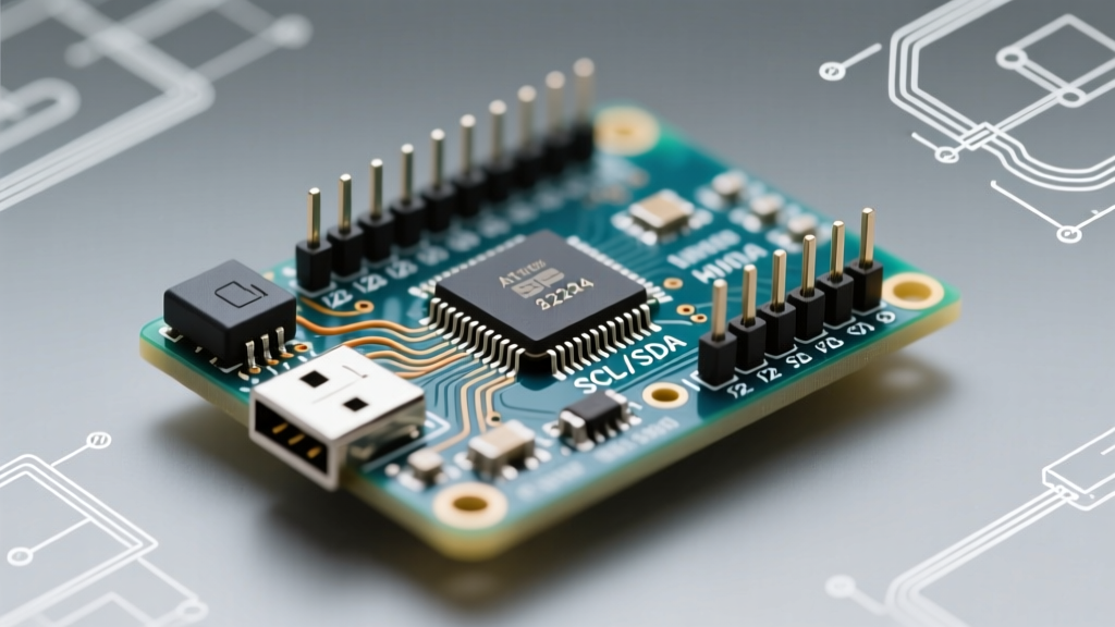
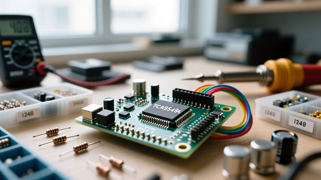
Modifying cheap Chinese breakout boards is a workflow killer. The traces are delicate, the flux requires cleaning, and the failure rate is high. By introducing an I2C multiplexer like the Texas Instruments TCA9548A, you route the main SDA/SCL lines into the MUX, which then fans out to eight independent downstream channels. Each channel acts as an isolated I2C bus. You can connect eight identical BME280 sensors, and the Arduino simply toggles the MUX channel before reading the sensor. No soldering iron required, no trace cutting, and zero hardware rework.
Strategic Hardware Selection: TCA9548A vs. PCA9546A
Optimizing your bill of materials (BOM) and prototyping speed requires choosing the right multiplexer for your specific topology. While the TCA9548A is the undisputed king of hobbyist breakouts, it is not always the optimal choice for production or compact wearable workflows.
| Multiplexer IC | Channels | Typical Breakout Cost | Best Workflow Use-Case | Package / Footprint |
|---|---|---|---|---|
| TCA9548A | 8 | $4.00 - $6.00 | Rapid prototyping, dense sensor arrays, robotics | TSSOP-24 / Adafruit Breakout |
| PCA9546A | 4 | $1.50 - $2.50 | Wearables, custom PCBs, low-channel-count nodes | SOIC-16 / QFN-16 |
| PCA9548A | 8 | $2.00 - $3.50 | Direct TCA9548A replacement for custom PCB fab | TSSOP-24 |
For rapid breadboarding, the Adafruit or SparkFun TCA9548A breakouts are unmatched. However, if you are designing a custom PCB in KiCad and only need to isolate three identical OLED displays, specifying a PCA9546A saves board space and reduces BOM costs. Both chips operate on the same fundamental I2C control register logic, meaning your C++ abstraction layer can remain identical across different hardware revisions.
The Pull-Up Resistor Trap: Parallel Resistance Math
The most common point of failure in i2c multiplexing workflows is ignoring bus capacitance and pull-up resistor parallelization. According to the NXP I2C-bus specification and user manual (UM10204), the I2C bus requires pull-up resistors to function, and the total resistance must keep the voltage drop within spec when a device pulls the line low (typically sinking 3mA).
Here is the workflow trap: Most cheap sensor breakout boards include 4.7kΩ pull-up resistors on their SDA and SCL lines. When you plug four of these sensors into four different channels of a TCA9548A, you might assume only one channel is active at a time, so the resistance is 4.7kΩ. However, if the MUX is not properly powered down, or if you are dealing with leakage currents across the MUX switches, those resistors can effectively parallelize. Furthermore, the MUX breakout itself usually includes 10kΩ upstream pull-ups.
To optimize your electrical workflow, always calculate the effective pull-up resistance using the formula:
1 / R_total = 1 / R_1 + 1 / R_2 + ... + 1 / R_n
If your effective resistance drops below 1.5kΩ on a 3.3V system, the I2C devices may not be able to sink enough current to pull the line below the logic-low threshold (0.3 * Vcc), resulting in phantom NACK errors and bus lockups. Workflow Tip: Use a multimeter to measure the resistance between VCC and SDA on your sensor modules. If they have onboard pull-ups, use a soldering iron to melt the jumper pads or desolate the resistors on all downstream devices, relying solely on the master pull-ups or the MUX's upstream pull-ups. For deep calculations, refer to the Texas Instruments SLVA704 application note on I2C Bus Pull-Up Resistor Calculation.
Software Architecture: Abstracting the Multiplexer
A poorly written I2C MUX implementation leads to spaghetti code, with channel-switching logic littered throughout your loop() function. To optimize your coding workflow, you must abstract the hardware layer from the sensor logic.
Instead of using the standard Adafruit wrapper which can sometimes hide the raw Wire mechanics, writing a lightweight channel-switching utility function keeps your memory footprint low and your logic clear. The TCA9548A listens on address 0x70. To select a channel, you simply write a single byte where the bits correspond to the channels (e.g., 0x01 for channel 0, 0x04 for channel 2).
void selectMuxChannel(uint8_t channel) {
  if (channel > 7) return; // Safety check
  Wire.beginTransmission(0x70);
  Wire.write(1 << channel);
  Wire.endTransmission();
}
By wrapping your sensor reading routines in a structured array or a state machine, you can iterate through the multiplexer channels cleanly. This abstraction means that if you later decide to replace the TCA9548A with a PCA9546A, or switch to a software I2C bit-bang routine, you only have to rewrite the selectMuxChannel() function. The rest of your application logic remains entirely untouched. This modularity is the hallmark of an optimized embedded software workflow.
Advanced Debugging: The MUX-Aware I2C Scanner
Every Arduino developer relies on the standard I2C Scanner sketch to debug wiring issues. However, the standard scanner is blind to devices hidden behind a multiplexer. When a sensor fails to initialize, guessing whether the issue is a bad jumper wire, a broken sensor, or a MUX channel failure wastes hours of development time.
Optimize your debugging workflow by keeping a custom 'MUX-Aware Scanner' in your personal snippet library. This script iterates through all 8 channels of the TCA9548A, runs the standard I2C scan on each downstream bus, and prints a formatted table to the Serial Monitor.
Expert Debugging Tip: If your MUX-Aware scanner shows that an entire channel is missing, but the sensor works when plugged directly into the main Arduino I2C bus, you are likely suffering from bus capacitance. Long wires between the MUX and the sensor act as capacitors, degrading the square wave into a sawtooth wave. Drop your Wire clock speed using Wire.setClock(100000); to give the signal more time to rise, or add local 2.2kΩ pull-up resistors directly at the sensor end of the wire.
Furthermore, when utilizing libraries like the Adafruit TCA9548A Learning Guide suggests, ensure you are not initializing all sensor objects in the global scope. Initialize them dynamically inside the loop after the MUX channel has been switched. Calling sensor.begin() before the MUX channel is routed will cause the library to cache a failure state, leading to silent data dropouts later in your execution cycle.
Summary Checklist for Deployment
To ensure your i2c multiplexing workflow is robust from breadboard to final enclosure, verify the following before finalizing your firmware:
- Address Map: Confirm the MUX address (0x70) does not conflict with other primary bus devices like RTC modules.
- Pull-Up Audit: Verify parallel resistance on downstream channels does not exceed the 3mA sink limit of your MCU's GPIO pins.
- Clock Speed: Explicitly define
Wire.setClock()based on your wire length and total bus capacitance (400pF limit for Fast Mode). - State Management: Ensure sensor libraries are initialized after the MUX channel is actively switched.
By treating i2c multiplexing not just as a hardware workaround, but as a core pillar of your system architecture, you eliminate physical rework, stabilize your codebase, and dramatically accelerate your path from prototype to production.