
The Anatomy of a Transformer: Identifying Primary and Secondary Windings
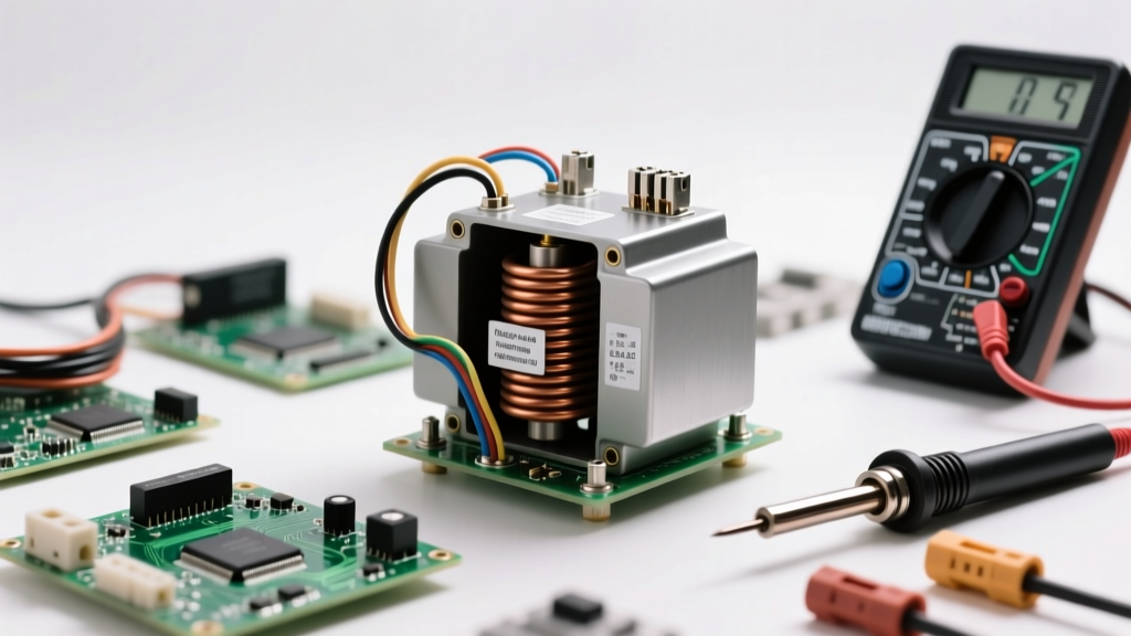
Before making any physical connections, you must understand the terminal designations. In North America, standard single-phase transformers follow NEMA and ANSI color-coding and labeling conventions. The primary (high voltage) windings are designated with H (e.g., H1, H2, H3, H4), while the secondary (low voltage) windings are designated with X (e.g., X1, X2, X3, X4).
A common and catastrophic mistake when learning how to wire a transformer with a dual-voltage primary (e.g., 120/240V) is misconfiguring the internal series/parallel jumpers. If your supply voltage is 240V, the primary coils must be wired in series. You achieve this by connecting H2 to H3, and applying your line voltage to H1 and H4. If your supply is 120V, the coils must be wired in parallel. You connect H1 to H3, and H2 to H4, then apply line voltage across the pairs. Reversing this configuration will result in a dead short, immediately tripping the breaker and likely destroying the transformer's internal thermal fuse.
Critical Safety Protocols Before You Make a Single Connection
Transformers are bidirectional devices. Even if the primary is de-energized, a backfeed from the secondary side can step up voltage to lethal levels on the primary terminals. Therefore, strict adherence to safety protocols is non-negotiable.
Lockout/Tagout (LOTO) and Verification
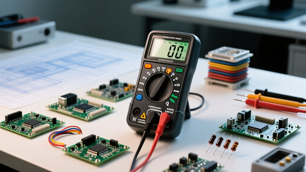
Always follow OSHA's Control of Hazardous Energy guidelines by applying a physical lockout to the upstream disconnect. Once locked out, verify the absence of voltage using a Category III or Category IV True-RMS multimeter. Test the meter on a known live source first (the Live-Dead-Live test), test the transformer terminals, and then test the known source again to ensure the meter did not fail during the process.
Expert Warning: Never assume a transformer is isolated just because the primary breaker is off. HVAC control circuits, multi-tap industrial panels, and parallel redundant systems can backfeed the secondary, stepping up to full primary voltage. Always test both H and X terminals.
Step-by-Step: How to Wire a Transformer (Primary Side)
The primary side connects to your main power source. The most critical aspect of primary wiring is selecting the correct overcurrent protection to handle both the continuous load and the initial magnetic inrush.
Sizing Overcurrent Protection (Fusing)
Transformers experience a massive inrush current—often 10 to 15 times the full load amperage (FLA)—for the first few AC cycles as the magnetic core saturates. If you use a standard fast-acting fuse, it will blow immediately upon energization. You must use Time-Delay (Slo-Blo) fuses.
According to NEC Article 450 overcurrent protection rules, if the primary current is less than 9 amps, you must size the fuse at no more than 167% of the primary FLA (or the next standard size up). If the primary current is 9 amps or more, size it at 125%. For example, a 500VA transformer on a 120V primary draws 4.16A. Multiplying by 167% yields 6.95A. The next standard fuse size is 8A. Therefore, an 8A time-delay fuse is required.
Wiring the Secondary Side: Load Matching and Grounding
The secondary side delivers the stepped-down (or stepped-up) voltage to your load. Proper grounding and bonding here are what ensure the safety of the downstream equipment and personnel.
The Grounding vs. Bonding Distinction
When wiring a standard 120V to 24V HVAC or industrial control transformer, the secondary is typically a two-wire system (X1 and X2). To establish a stable reference to earth and provide a safe fault-current path, you must bond the X2 terminal to the equipment grounding conductor (EGC) or the metal chassis. This prevents the secondary circuit from 'floating' to dangerous static or induced voltages. If the transformer features a center-tapped secondary (e.g., 120/240V or 24V CT), the center tap (usually X2) is your neutral/ground bond point, while X1 and X3 provide the line voltages.
Transformer Wiring Gauge & Torque Specifications
Using undersized wire on the secondary side is a leading cause of transformer overheating and voltage drop. Because secondary current is inversely proportional to the voltage step-down, a 120V to 24V transformer will see a current multiplication of 5x on the secondary. Below is a reference chart for common single-phase control and isolation transformers.
| Transformer VA | Primary Voltage | Primary FLA | Min Primary AWG | Secondary Voltage | Secondary FLA | Min Secondary AWG |
|---|---|---|---|---|---|---|
| 40 VA | 120V | 0.33A | 18 AWG (14 Rec.) | 24V | 1.67A | 14 AWG |
| 150 VA | 240V | 0.62A | 14 AWG | 120V | 1.25A | 14 AWG |
| 300 VA | 120V | 2.50A | 14 AWG | 24V | 12.5A | 10 AWG |
| 500 VA | 120V | 4.16A | 12 AWG | 24V | 20.8A | 8 AWG |
Note: While 18 AWG may mathematically handle the amperage for small primaries, NEC Chapter 3 and general mechanical best practices dictate using a minimum of 14 AWG for physical durability and terminal screw engagement.
When terminating wires under the transformer's lug plates, do not guess the tightness. Use a calibrated torque screwdriver. Most small control transformers require between 12 to 18 in-lbs of torque. Over-torquing strips the brass threads, while under-torquing creates high-resistance connections that generate localized heat and lead to premature failure.
Common Wiring Failure Modes and How to Prevent Them
Even with correct wire sizing, transformers fail due to environmental and electrical stresses. Understanding these failure modes is key to long-term reliability.
- Shorted Secondary Turns: Caused by insulation breakdown due to excessive heat or moisture ingress. This results in high primary current and low secondary voltage. Prevention: Ensure the enclosure is NEMA-rated for the environment (e.g., NEMA 3R for outdoor damp locations).
- Blown Internal Thermal Fuse: Most modern epoxy-encapsulated transformers have a non-resettable thermal fuse buried deep inside the primary winding. If you wire the primary jumpers incorrectly (e.g., parallel instead of series), the resulting massive current spike will blow this fuse instantly. The transformer will read as an 'open' circuit and must be replaced.
- Core Saturation from Overvoltage: Supplying 130V to a transformer rated for 110V pushes the magnetic core into saturation. This causes excessive humming, extreme heat, and eventual insulation failure. Always match the primary tap to your actual measured supply voltage, not just the nominal panel voltage.
Expert Troubleshooting: When the Secondary Outputs Zero Volts
If you have wired the transformer, applied power, and the secondary reads 0V, follow Fluke's transformer testing methodologies to isolate the fault safely:
- Verify Primary Voltage: Measure across H1 and H4 (or your specific primary terminals). If you read 0V, the issue is upstream (blown primary fuse, tripped breaker, or open disconnect).
- Check for Internal Opens: De-energize and LOTO the circuit. Switch your multimeter to resistance (Ohms). Measure across the primary terminals. A healthy primary winding will typically read between 2 and 15 Ohms depending on the VA rating. If it reads 'OL' (Over Limit / Infinite), the internal thermal fuse has blown.
- Check Secondary Continuity: Measure across X1 and X2. The resistance should be very low (usually under 2 Ohms for large transformers, slightly higher for tiny 20VA units). If it reads 'OL', the secondary winding is severed.
- Check for Ground Faults: Measure resistance from X1 to the transformer chassis/ground, and X2 to the chassis. It should read 'OL'. If it reads continuity, the winding insulation has failed and is shorting to the core.
Mastering the safe installation and troubleshooting of transformers requires a meticulous approach to polarity, overcurrent protection, and grounding. By respecting the magnetic and thermal limits of the equipment, you ensure a reliable power distribution system that operates safely for decades.