
The Anatomy of the Dial: Beyond the Basic Symbols
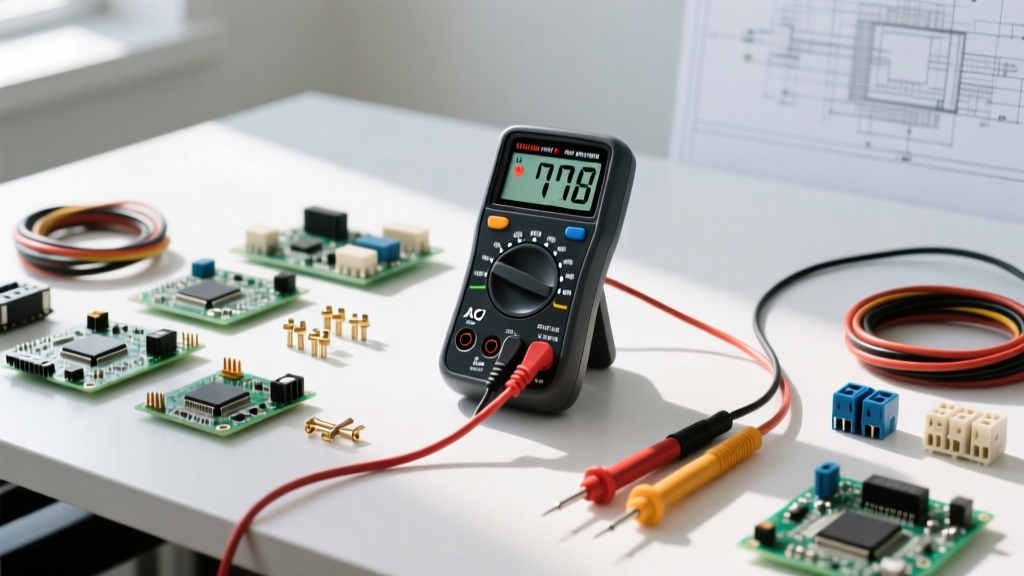
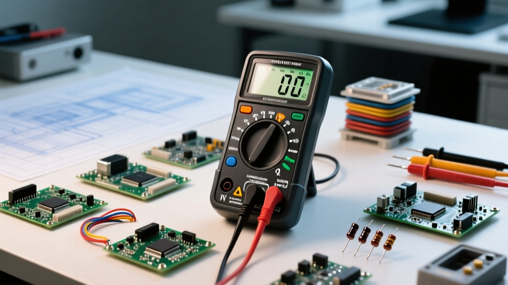
When you pick up a digital multimeter (DMM), the rotary dial is your primary interface. However, truly understanding the settings on a multimeter goes far beyond simply matching symbols to wires. Every position on the dial reconfigures the internal circuitry of the meter, altering how it interacts with the device under test (DUT). Whether you are using a budget-friendly Klein Tools MM400 or a professional-grade Fluke 117, knowing the internal mechanics of these settings is what separates a novice from a seasoned electronics technician.
In this fundamentals explainer, we will decode the settings on a multimeter, exploring the internal Analog-to-Digital Converter (ADC) configurations, shunt resistors, and signal injection methods that make your measurements possible.
Voltage Settings (V⎓ and V~): Internal Impedance and Auto-Ranging
Voltage measurement is the most common function of any DMM. The dial typically splits this into Direct Current (V⎓ or VDC) and Alternating Current (V~ or VAC). But what happens when you turn the dial to these settings?
The 10 Megohm Standard
When set to voltage mode, the multimeter configures its internal ADC to act as a high-impedance voltmeter. Standard DMMs utilize a 10 MΩ (megohm) input impedance. This high resistance ensures that the meter draws virtually zero current from the circuit, preventing the meter itself from altering the voltage it is trying to measure—a phenomenon known as 'loading'. If you are measuring high-impedance circuits, such as automotive sensor networks or vacuum tube audio equipment, this 10 MΩ setting can still load the circuit. In these niche cases, technicians use a 'LoZ' (Low Impedance) setting, available on advanced meters like the Fluke 117, which drops the impedance to roughly 3 kΩ to bleed off ghost voltages.
True-RMS vs. Average Responding
On the V~ setting, cheaper multimeters use an 'average-responding' circuit that assumes a perfect sine wave, multiplying the average voltage by 1.111 to display the RMS value. If you measure a non-linear load (like a dimmer switch or a variable frequency drive), this setting will yield wildly inaccurate results. A 'True-RMS' setting utilizes a specialized internal thermal or computational converter to calculate the actual heating value of the waveform, providing accurate readings regardless of wave distortion.
Current Settings (A, mA, µA): The Shunt Resistor and Burden Voltage
Current settings are arguably the most misunderstood and dangerous settings on a multimeter. Unlike voltage settings, which are placed in parallel, current settings require the meter to be placed in series with the circuit. To measure current, the DMM routes the incoming electricity through an internal precision resistor called a 'shunt'.
The Dual-Shunt Architecture
Most multimeters feature two distinct current settings and corresponding probe ports:
- The 10A (or 20A) Setting: This routes current through a thick, ultra-low resistance shunt (typically around 0.01 Ω). Because the resistance is so low, it generates minimal heat and alters the circuit's voltage very little.
- The mA/µA Setting: This routes current through a much higher resistance shunt (often 1 Ω to 10 Ω) to generate a measurable voltage drop for the ADC at micro-amp levels.
The Burden Voltage Trap
According to SparkFun's multimeter tutorial, the resistance of the mA shunt creates a voltage drop known as 'burden voltage'. If you attempt to measure a 3.3V microcontroller circuit drawing 100mA using the mA setting with a 1 Ω shunt, the meter will drop 0.1V. Your circuit is now only receiving 3.2V, which might cause a brownout reset. Understanding this setting limitation is critical for low-voltage embedded systems debugging.
Resistance, Continuity, and Diode Mode: Signal Injection
When you switch to the Ohms (Ω), Continuity, or Diode settings, the multimeter fundamentally changes its operating mode. Instead of passively measuring existing electrical potential, the meter's internal battery actively injects a known test current into the circuit and measures the resulting voltage drop.
Resistance (Ω) and Auto-Ranging
In resistance mode, the meter sources a precise micro-amp current. By applying Ohm's Law (R = V/I), the internal processor calculates the resistance. On manual-ranging meters, selecting a lower resistance setting (e.g., 200 Ω) forces the meter to output a higher test current for better resolution. However, applying this higher current to sensitive components like thermistors can cause self-heating, skewing your reading.
Continuity vs. Diode Test
While both settings emit an audible tone or display a value, their internal test voltages differ drastically:
- Continuity Mode: Typically outputs an open-circuit voltage of less than 1.0V. This is intentionally low so that testing continuity across a semiconductor junction will not accidentally forward-bias and turn on the component.
- Diode Mode: Outputs a higher open-circuit voltage (usually between 1.5V and 3.0V) with a test current of roughly 1mA. This specific setting is designed to overcome the forward voltage barrier of a PN junction. It will read ~0.6V for standard silicon diodes and between 1.8V and 3.3V for LEDs, allowing you to test LED polarity without removing them from a breadboard.
Quick Reference: Dial Symbols and Real-World Applications
| Dial Symbol | Setting Name | Internal Action | Primary Use Case |
|---|---|---|---|
| V⎓ / VDC | DC Voltage | High-Z parallel sampling | Batteries, logic levels, DC power supplies |
| V~ / VAC | AC Voltage | High-Z parallel sampling (RMS) | Mains outlets, transformers, HVAC controls |
| Ω | Resistance | Sources micro-amps, measures drop | Checking resistors, heating elements, traces |
| -|)- | Continuity | Sources low-V current, triggers comparator | Verifying solder joints, finding broken wires |
| ->|- | Diode Test | Sources 1.5V-3V at ~1mA | Checking PN junctions, LED polarity, BJT legs |
| A / mA | Current | Routes through internal shunt resistor | Measuring motor draw, circuit power consumption |
Advanced Settings: Capacitance, Frequency, and hFE
Modern mid-tier DMMs, such as the highly regarded Brymen BM235, include specialized settings that require complex internal timing circuits.
- Capacitance (F): The meter charges the capacitor with a known constant current and measures the time it takes to reach a specific voltage threshold. Because of this charging cycle, measuring large capacitors (e.g., 10,000 µF) can take several seconds. Always discharge capacitors before using this setting, or you risk destroying the meter's internal protection transistors.
- Frequency (Hz) and Duty Cycle (%): These settings utilize an internal comparator and counter to track zero-crossings in an AC waveform. This is essential for diagnosing PWM (Pulse Width Modulation) signals in automotive fuel injectors or motor controllers.
- hFE (Transistor Gain): A niche setting that physically biases a bipolar junction transistor (BJT) plugged into the meter's front port, measuring the ratio of collector current to base current. While useful for quick sorting, it lacks the precision of a dedicated curve tracer.
Fatal Setting Mistakes and How to Avoid Them
Misunderstanding the settings on a multimeter doesn't just lead to bad data; it can lead to catastrophic equipment failure or personal injury. The most infamous error in electronics is measuring voltage while the probes are plugged into the current (A) jacks.
When the dial is set to Voltage, but the red probe is in the 10A port, you are effectively placing a 0.01 Ω dead short across your voltage source. If the source has high fault-current capability (like a mains panel or a car battery), the resulting arc flash can vaporize the internal shunt, melt the probe tips, and cause severe burns.
To mitigate this, always look for meters with 'Input Alert' features, which beep angrily if the dial is on a voltage setting while the lead is in the current jack. Furthermore, always respect the CAT (Category) ratings printed on the dial and casing. A CAT III 600V rating means the internal clearances and arc-suppression components are designed to withstand the explosive energy of a transient spike in a hard-wired building distribution system, a protection level absent in cheap, unrated multimeters.
Summary
Mastering the settings on a multimeter requires a mental shift from viewing the tool as a simple display to understanding it as a reconfigurable test instrument. By respecting the burden voltage on current settings, understanding the injection currents of diode modes, and recognizing the impedance characteristics of voltage settings, you will drastically improve your diagnostic accuracy and ensure your safety in the field. For further reading on safety standards, refer to the official Fluke guide on multimeter usage and CAT ratings.