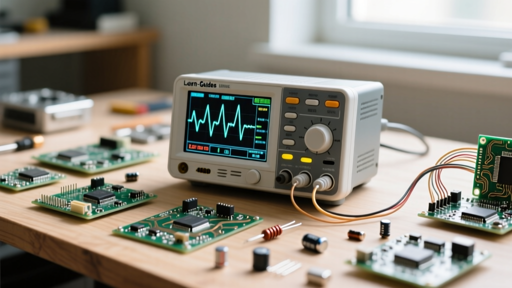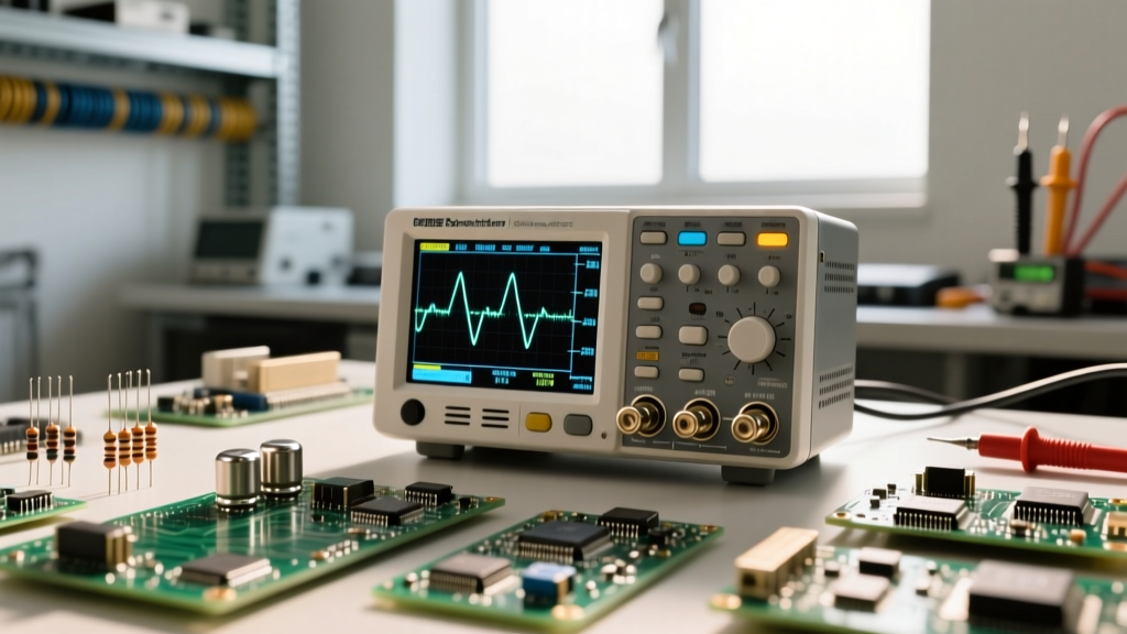

When you first unbox an oscilloscope, the largest number printed on the front panel is usually the bandwidth. For beginners, this number feels like a simple "higher is better" metric, much like horsepower in a car. However, as you transition from blinking LEDs to debugging high-speed SPI buses or switching power supplies, you quickly learn that oscilloscope bandwidth is the fundamental arbiter of your measurement truth. If you misunderstand it, you will chase ghosts, misinterpret signal integrity issues, and waste hours debugging phantom timing errors.
This guide is structured as a skill-building path. We will move from the foundational physics of bandwidth to practical decision matrices, ensuring you know exactly how to match your test equipment to your evolving electronics projects.
The Foundation: What Oscilloscope Bandwidth Actually Means
In the realm of test and measurement, bandwidth is not the highest frequency a signal can pass through; it is the frequency at which the input signal is attenuated by exactly 3 decibels (-3dB).
What does a -3dB drop mean in practical terms? It means the amplitude of the signal is reduced to 70.7% of its actual value. If you feed a perfect 1.0V peak-to-peak sine wave at 100 MHz into a 100 MHz oscilloscope, the scope will display a waveform measuring only 0.707V. That is a 30% amplitude error. According to the Tektronix Oscilloscope Basics Guide, measuring a digital clock signal at the exact bandwidth limit of your scope will result in severely rounded edges, completely masking the true rise time and hiding potential ground bounce or overshoot.
"The system bandwidth is always limited by the weakest link in the measurement chain. A 500 MHz scope paired with a 50 MHz probe yields a 50 MHz measurement system."
The Skill Progression: Matching Bandwidth to Your Projects
As your skills grow, so do the frequencies of the signals you need to analyze. Here is how to map oscilloscope bandwidth to your current skill tier.
Level 1: Audio, Power Supplies, and Low-Frequency Analog
If you are designing audio amplifiers, analyzing analog sensor outputs, or measuring the ripple on a linear power supply, your signals rarely exceed a few megahertz. A 20 MHz to 50 MHz oscilloscope is perfectly adequate. Entry-level workhorses like the Rigol DS1054Z (50 MHz) or Siglent SDS1104X-E (100 MHz) provide more than enough bandwidth to capture audio harmonics and low-frequency PWM signals without breaking the budget.
Level 2: Microcontrollers and Embedded Digital Protocols
Once you start debugging I2C, SPI, UART, or CAN bus protocols, the rules change. Digital signals are square waves, which are mathematically composed of a fundamental frequency plus infinite odd harmonics (3rd, 5th, 7th, etc.). To accurately reconstruct the square shape and see the fast edges, you must capture at least the 5th harmonic.
If you are measuring an SPI clock running at 20 MHz, the 5th harmonic is 100 MHz. Therefore, you need a scope with a minimum bandwidth of 100 MHz to 200 MHz. Scopes like the Siglent SDS1204X-E (200 MHz) are the sweet spot for intermediate embedded engineers.
Level 3: High-Speed Digital, RF, and Fast Edge Rates
When you graduate to DDR memory interfaces, USB 2.0, Ethernet, or RF mixing circuits, you are no longer just looking at clock frequencies; you are analyzing edge rates. A 50 MHz clock might have a rise time of 500 picoseconds, generating harmonic content well into the gigahertz range. For these applications, you need 350 MHz to 1 GHz+ bandwidth, utilizing advanced models like the Keysight InfiniiVision 1200 X-Series or high-end Teledyne LeCroy WaveRunner systems.
The Math Behind the Glass: Rise Time and the Knee Frequency
Advanced users do not select oscilloscope bandwidth based solely on the clock frequency; they select it based on the signal's rise time ($t_r$). The relationship between bandwidth (BW) and rise time for scopes with a Gaussian frequency response is defined by the formula:
BW = 0.35 / $t_r$
Note: Modern high-end digital storage oscilloscopes (DSOs) with brick-wall filter responses may use a constant closer to 0.45.
To ensure your scope does not artificially slow down the measured rise time, Keysight's evaluation guides recommend that the oscilloscope's rise time should be at least three to five times faster than the signal's rise time. Below is a reference table mapping bandwidth to intrinsic rise time capabilities:
| Oscilloscope Bandwidth | Intrinsic Rise Time (10-90%) | Max Recommended Signal Rise Time | Typical Application |
|---|---|---|---|
| 50 MHz | 7.0 ns | ~35 ns | Audio, Basic PWM, I2C |
| 100 MHz | 3.5 ns | ~17 ns | SPI, UART, Motor Control |
| 200 MHz | 1.75 ns | ~8.7 ns | Fast SPI, 10/100 Ethernet |
| 500 MHz | 700 ps | ~3.5 ns | USB 2.0, High-Speed ADCs |
| 1 GHz | 350 ps | ~1.7 ns | DDR3/4, PCIe, RF |
The Hidden Bottleneck: Probe Bandwidth and Capacitive Loading
A common trap for intermediate engineers is buying a 200 MHz oscilloscope and using cheap, low-bandwidth probes, entirely bottlenecking the system. But the issue goes deeper than just the probe's printed bandwidth rating; it is about capacitive loading.
Every oscilloscope probe acts as a capacitor in parallel with your circuit. A standard passive 10:1 probe might have an input capacitance of 12pF to 15pF. At high frequencies, this capacitance creates a low-impedance path to ground, literally draining the high-frequency energy out of your circuit.
- The 1:1 Probe Trap: Many kits include a switchable 1:1 / 10:1 probe. In 1:1 mode, the bandwidth drops to roughly 5 MHz to 10 MHz, and the capacitive load skyrockets to 100pF or more. Never use 1:1 mode for digital signals.
- Active FET Probes: For high-speed digital work (Level 3), you must invest in active probes. These feature input capacitances as low as 1pF, preserving signal integrity and preventing the probe from altering the circuit's behavior.
Decision Matrix: Selecting Your Next Oscilloscope
Use this matrix to align your purchasing decision with your current skill level and project roadmap.
| Skill Tier | Target Bandwidth | Minimum Sample Rate | Example Models (Approx. Pricing) |
|---|---|---|---|
| Beginner / Hobbyist | 50 MHz - 70 MHz | 500 MSa/s | Rigol DS1054Z (~$350) |
| Intermediate / Embedded | 100 MHz - 200 MHz | 1 GSa/s - 2 GSa/s | Siglent SDS1204X-E (~$450), Keysight DSOX1204G (~$1,400) |
| Advanced / Signal Integrity | 350 MHz - 1 GHz | 4 GSa/s+ | Keysight InfiniiVision 3000G X-Series (~$5,000+) |
Common Failure Modes When Ignoring Bandwidth Limits
What happens when you push a scope beyond its bandwidth limits in a real-world debugging scenario? Consider a failure mode involving a failing SPI flash memory chip. The microcontroller is sending a 40 MHz clock. You hook up your 50 MHz oscilloscope to verify the clock signal.
Because 40 MHz is near the 50 MHz -3dB limit, the scope attenuates the high-frequency harmonics that make up the square wave's sharp corners. On your screen, the clock looks like a smooth, rounded sine wave. You measure the rise time, and it appears slow but within the flash chip's datasheet specifications. You conclude the clock is fine and waste three days rewriting your SPI driver software.
In reality, the microcontroller was outputting a square wave with severe overshoot and ringing that violated the flash chip's absolute maximum voltage ratings, causing it to lock up. A 200 MHz oscilloscope would have easily captured the 5th harmonic (200 MHz), revealing the sharp edges, the 1.5V overshoot, and the true root cause of the hardware failure.
Mastering oscilloscope bandwidth is not just about reading a spec sheet; it is about understanding the physics of signal reconstruction. By applying the 5x rule for digital signals, calculating rise time requirements, and respecting probe loading, you transition from merely looking at waveforms to truly understanding the electrical behavior of your designs.