
The Thermodynamics of Desoldering: Why Beginners Struggle
Desoldering is fundamentally more challenging than soldering. When you first solder a joint, the manufacturer's flux is pristine, the copper pads are unoxidized, and the thermal profile is predictable. When you attempt to remove that same component, you are fighting physics and chemistry. The original flux has long since burned away, leaving behind oxidized copper and a rigid intermetallic layer. If you simply apply heat without a strategy, you will transfer excessive thermal energy into the FR-4 fiberglass substrate, risking catastrophic pad delamination.
Understanding how to desolder properly requires recognizing the concept of thermal mass. A thick ground plane will wick heat away from your soldering iron tip faster than a thin signal trace. Beginners often compensate for this by leaving the iron on the joint for 10 to 15 seconds, which exceeds the glass transition temperature (Tg) of standard FR-4 (typically around 130°C to 140°C). When the resin softens, the copper pad detaches. This guide provides a structured, professional walkthrough to extract both through-hole and surface-mount components while preserving the integrity of your printed circuit board.
The Desoldering Arsenal: Tools and Specifications
Attempting to remove components with only a soldering iron and a pair of tweezers is a recipe for destroyed PCBs. According to the IPC-7711/7721 Standard for Rework and Repair, proper tool selection is critical for minimizing thermal shock. Below is a comparison matrix of the essential tools you need, complete with specific model recommendations used by professional rework technicians.
| Tool Category | Model Recommendation | Average Price | Best Application |
|---|---|---|---|
| Manual Desoldering Pump | Engineer SS-02 | $22 | Through-hole capacitors, resistors, and connectors |
| Solder Wick (Braid) | Goot Wick CP-2060 | $8 | SMD pad cleanup, via clearing, and fine-pitch ICs |
| Electric Desoldering Gun | Hakko FR-301 | $260 | High-volume through-hole teardowns and multi-layer boards |
| Hot Air Rework Station | Quick 861DW | $240 | Multi-pin SMD ICs, QFN packages, and BGAs |
| No-Clean Flux Gel | Chip Quik SMD291AX | $12 | Reactivating oxidized joints before heat application |
For a beginner, the Engineer SS-02 manual pump and a spool of Goot Wick are mandatory. The SS-02 features a fluorocarbon rubber seal and a Teflon-coated nozzle, which prevents molten solder from adhering to the tip—a common failure point in cheaper $5 alternatives.
Step-by-Step Walkthrough: Extracting a Through-Hole Component
Removing a through-hole component, such as an electrolytic capacitor or a DIP IC, requires managing the solder inside the plated through-hole (PTH) via. If solder remains in the barrel, forcing the component out will rip the copper plating from the inside of the hole.
Step 1: Flux Reactivation
Never apply heat to a dry, oxidized joint. Dispense a small amount of no-clean flux gel directly onto the solder joints you intend to remove. The flux will lower the surface tension of the molten solder and break down metal oxides, allowing the solder to flow freely into your extraction tool. As noted in Adafruit's Guide to Excellent Soldering, adding fresh solder (tinning) to an old, stubborn joint before desoldering can also introduce fresh flux and improve thermal transfer.
Step 2: The Heat and Pump Technique
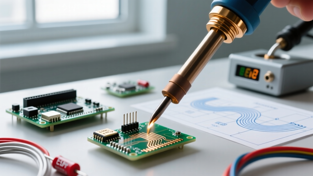
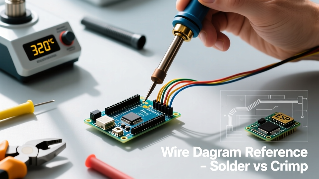
Set your soldering iron to 350°C (if using lead-free SAC305 solder) or 320°C (for traditional Sn60/Pb40 leaded solder). Wrap the component lead with the iron tip to maximize surface contact. Wait exactly 2 to 3 seconds for the solder to become fully liquid and shiny. Remove the iron and immediately place the nozzle of the Engineer SS-02 pump directly over the molten joint. Depress the trigger. The vacuum will violently pull the liquid solder out of the via.
Step 3: Clearance Verification
Inspect the hole under a magnifying lamp. You should see a clear ring of light passing through the via, indicating the lead is no longer mechanically bonded to the barrel. If solder remains, reapply flux and repeat the process. Never pull on the component while the solder is solid.
Advanced Extraction: Removing an SMD IC Without Hot Air
Beginners often lack a hot air rework station but still need to remove Surface Mount Device (SMD) integrated circuits, such as an SOIC-8 chip. You can achieve this using the 'solder wick drag' method, though it requires immense patience.
- Flood the Pins: Apply flux to all pins on one side of the IC. Use your iron to add a generous amount of fresh leaded solder to the pins. This creates a high-thermal-mass bridge that keeps all pins molten simultaneously.
- The Drag: While keeping the iron moving back and forth to maintain the molten state, use a precision scalpel (like an X-Acto #11) to gently pry up the leads on that side. Once the pins lift off the pads, the IC will pivot.
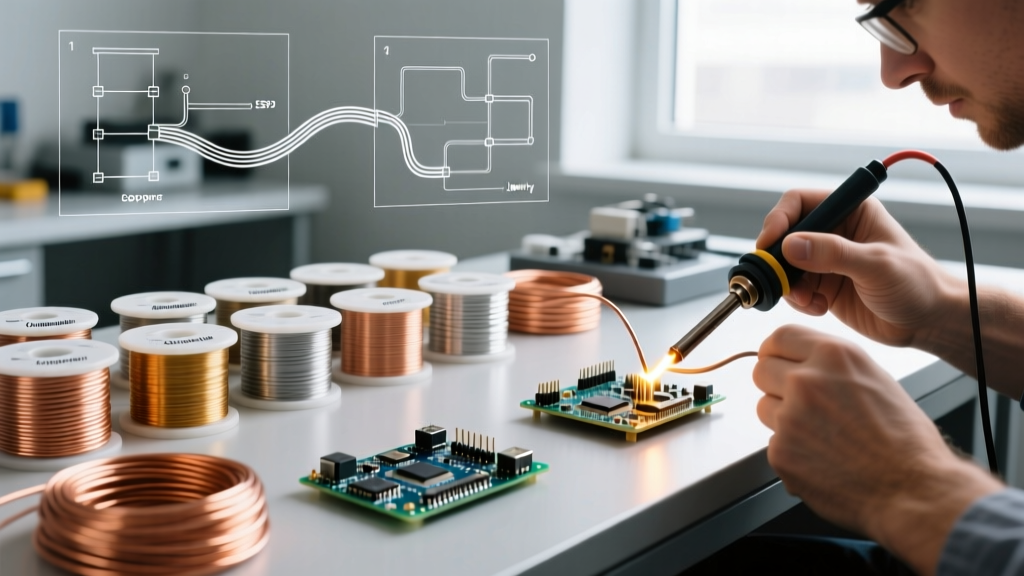
- Wick the Pads: With the component removed, the PCB pads will be covered in uneven solder. Place a 2.0mm wide Goot Wick over the pads, apply flux, and drag your 350°C iron over the braid. The capillary action of the woven copper will absorb the excess solder, leaving perfectly flat, pristine pads ready for a replacement chip.
Diagnosing and Repairing Thermal Damage
Even with perfect technique, accidents happen. The most common failure mode when learning how to desolder is a lifted pad. This occurs when the adhesive bonding the copper to the FR-4 substrate fails due to prolonged heat exposure.
The Kynar Wire Bypass
If a pad rips off the board and hangs from the component lead, do not panic, and do not attempt to glue it back down. According to SparkFun's Through-Hole Soldering Tutorial, proper rework involves creating a mechanical bypass. Scrape away the solder mask from the trace leading to the lifted pad using a fiberglass scratch pen until bare copper is exposed. Cut a piece of 30 AWG Kynar (PTFE insulated) wire. Solder one end to the exposed trace and the other end directly to the component lead. Secure the wire to the board using a drop of UV-curable solder mask or cyanoacrylate adhesive to provide strain relief.
Post-Rework Chemical Cleaning Protocols
Flux residue, particularly from rosin-based (RMA) or organic acid (OA) fluxes, can become conductive or corrosive over time, leading to parasitic capacitance or dendritic growth. After every desoldering operation, you must clean the work area.
- Use 99% Isopropyl Alcohol (IPA). Lower concentrations contain too much water, which can trap flux residue under components.
- Apply the IPA using a lint-free wipe (Kimwipes) or an ESD-safe hog-hair brush.
- Scrub in a circular motion to dissolve the rosin, then wipe away the dirty alcohol before it evaporates and redeposits the flux onto the board.
Mastering the art of desoldering transforms you from a hobbyist who can only build new circuits into a technician capable of diagnosing, repairing, and salvaging complex electronics. Respect the thermal limits of your materials, maintain your tools, and always rely on fresh flux to do the heavy lifting.