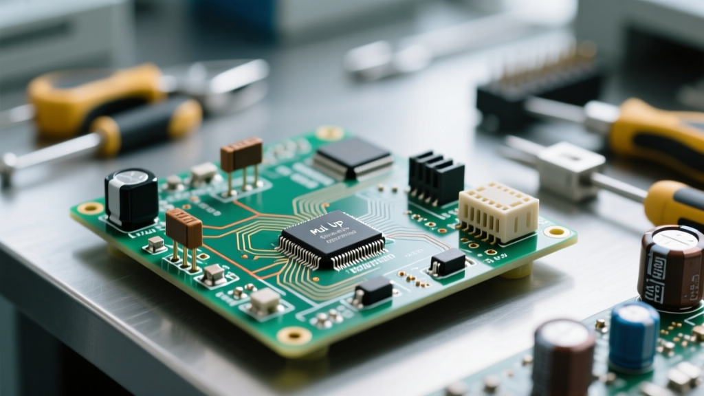

The Core Mechanics: Inside the Resistive Track
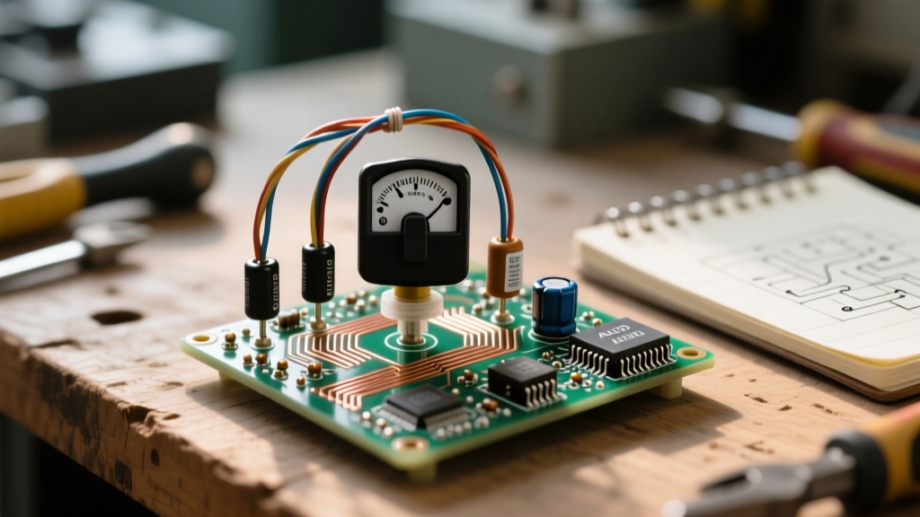
When prototyping analog circuits or debugging audio equipment, the question 'potentiometer how does it work' extends far beyond basic textbook theory. At a physical level, a potentiometer (often abbreviated as a 'pot') is a three-terminal electromechanical transducer that acts as an adjustable voltage divider. However, to truly master component selection and circuit debugging, you must understand the material science of the resistive track and how it dictates measurement signatures.
The resistive element is the heart of the component. Different materials yield vastly different electrical characteristics, temperature coefficients (tempco), and lifespans:
- Carbon Composition: Common in audio applications (e.g., ALPS RK09 series). They offer high resolution and low current noise but suffer from poor temperature stability and mechanical wear over time.
- Cermet (Ceramic-Metal): The standard for precision trimming (e.g., the ubiquitous Bourns 3296W multi-turn trimpot). Cermet tracks offer excellent tempco (typically ±100 ppm/°C) and high power dissipation, making them ideal for calibration circuits.
- Conductive Plastic: Used in high-end joysticks and studio faders. They provide exceptional wiper contact reliability and lifespans exceeding 1,000,000 cycles, though they are sensitive to high-temperature soldering.
According to Wikipedia's comprehensive breakdown of potentiometer mechanics, the physical wiper—a spring-loaded metal or carbon brush—slides across this track, effectively splitting the total resistance into two series resistors.
The Voltage Divider Principle in Action
To understand how a potentiometer works in a live circuit, we must look at the voltage divider equation. When wired with three terminals (Terminal 1 to Ground, Terminal 3 to Vcc, and Terminal 2 as the Wiper output), the pot divides the input voltage based on the physical position of the shaft.
Vout = Vin × [ R2 / (R1 + R2) ]
Where R1 is the resistance between the CCW terminal and the wiper, and R2 is the resistance between the wiper and the CW terminal.
This principle is foundational to analog signal processing. For a deeper dive into the math and practical applications of this circuit topology, refer to SparkFun's voltage divider tutorial. If you only need a variable resistor (rheostat mode), you short the wiper (Terminal 2) to one of the outer terminals, ensuring that if the wiper loses contact, the circuit fails safely to maximum resistance rather than dropping to zero.
Hands-On Testing: Measuring Potentiometer Health
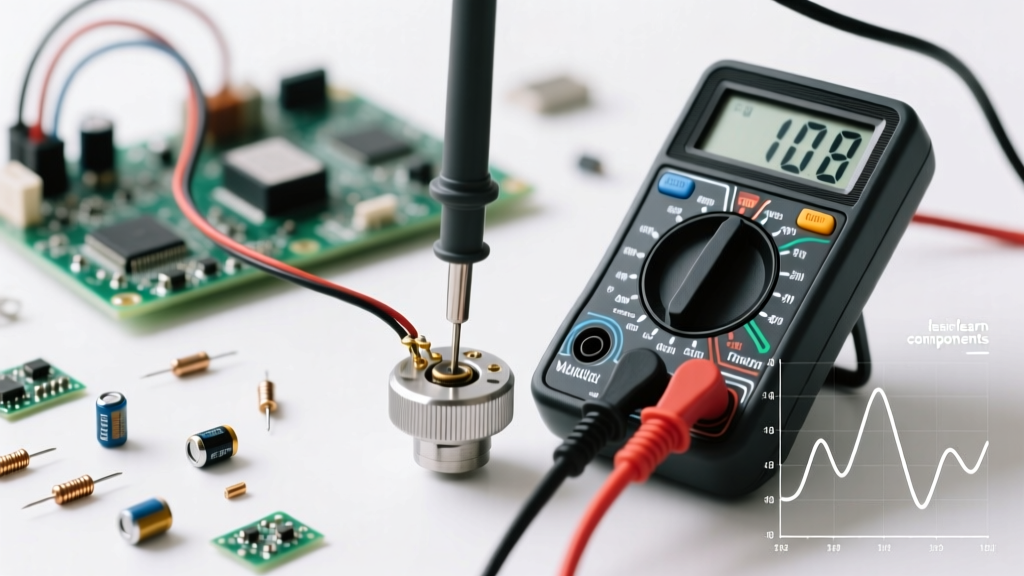
Testing a potentiometer requires a methodical approach using both a Digital Multimeter (DMM) and, for advanced diagnostics, an oscilloscope. Here is a professional testing framework.
Step 1: Static Resistance and Tolerance Verification
Before applying power, isolate the component from the circuit. Set your DMM to the appropriate resistance range and measure across Terminal 1 and Terminal 3. For a 10kΩ pot with a ±20% tolerance (standard for carbon), your reading should fall between 8kΩ and 12kΩ. If the DMM reads 'OL' (Open Loop), the internal resistive track is fractured, a common failure mode in cheap carbon pots subjected to mechanical over-rotation.
Step 2: Dynamic Tracking and Wiper Continuity
Connect your DMM probes to Terminal 1 and Terminal 2 (the wiper). Slowly rotate the shaft from the minimum to the maximum position. The resistance should increase smoothly and monotonically. Information Gain: If you observe sudden jumps or drops in resistance on the DMM display, the wiper is bouncing or the track has localized oxidation. This 'dead spot' will introduce severe crackling in audio circuits or erratic behavior in microcontroller ADC inputs.
Step 3: Advanced Diagnostics with an Oscilloscope
A DMM is too slow to catch microsecond wiper bounces. To measure Equivalent Noise Resistance (ENR) and dynamic contact stability, use an oscilloscope:
- Wire the potentiometer as a voltage divider across a clean, regulated 5V DC supply.
- Connect the oscilloscope probe to the wiper (Terminal 2).
- Set the scope to AC coupling with a high sensitivity (e.g., 10mV/div) and a fast timebase.
- Slowly rotate the shaft. A healthy cermet or conductive plastic pot will show a flat, noise-free baseline. A degraded carbon pot will display high-frequency voltage spikes, indicating wiper bounce and contact resistance fluctuations.
Analyzing Taper: Linear vs. Logarithmic Curves
The 'taper' defines the mathematical relationship between the shaft's physical rotation angle and the resulting resistance ratio. Misidentifying a taper is a frequent prototyping error that leads to non-linear sensor readings or unnatural audio volume controls. The table below outlines how to identify tapers using a multimeter at the exact mechanical midpoint (50% rotation).
| Taper Type | Industry Code | Resistance at 50% Rotation | Primary Use Case |
|---|---|---|---|
| Linear | B (or Lin) | ~50% of Total R | Position sensors, ADC inputs, bias trimming |
| Logarithmic (Audio) | A (or Log) | ~10% to 15% of Total R | Audio volume controls (matches human hearing) |
| Reverse Logarithmic | C (or Anti-Log) | ~85% to 90% of Total R | Specific audio pan pots, specialized gain staging |
Testing Tip: To definitively identify an unknown potentiometer's taper, measure Terminal 1 to Wiper at the 25%, 50%, and 75% physical marks. Plotting these three data points will immediately reveal the curve's geometry.
Real-World Failure Modes and Troubleshooting
Understanding how a potentiometer works also means understanding how it fails. When reviewing Bourns' potentiometer selection guides and reliability datasheets, several environmental and mechanical failure modes stand out:
- Track Wear (Mechanical Degradation): After hundreds of thousands of cycles, the wiper physically gouges the resistive material, creating non-conductive dust. This manifests as localized open circuits. Fix: Replace with a conductive plastic or multi-turn cermet alternative.
- Moisture Ingress and Galvanic Corrosion: In high-humidity environments, moisture penetrates the casing, causing silver migration or oxidation on the wiper contact point. This results in a drifting baseline resistance. Fix: Specify sealed potentiometers (IP67 rated) or apply conformal coating to the PCB area surrounding the component.
- Thermal Drift: If used as a rheostat to drop significant current, the internal temperature rises. Carbon pots have a negative temperature coefficient (resistance drops as it heats), which can lead to thermal runaway in poorly designed power circuits. Always check the power dissipation rating (e.g., 0.5W for standard 16mm pots) and derate by 50% for safety.
Summary for Prototypers
Mastering the potentiometer requires moving past the basic 'variable resistor' definition. By applying rigorous testing methodologies—verifying static tolerances, analyzing dynamic wiper noise via oscilloscope, and correctly mapping tapers—you ensure signal integrity in your prototypes. Whether you are designing a high-fidelity audio preamp or a precision robotics feedback loop, the measurement techniques outlined above will save hours of debugging and elevate your hardware design.