
The HC-05 BT Module: Beyond the Basic Blink
The HC-05 BT module is arguably the most ubiquitous wireless UART transceiver in the DIY electronics and prototyping space. Built around the CSR BC417 Bluetooth 2.0+EDR chip, it operates on the Serial Port Profile (SPP), allowing it to emulate a standard serial cable over the air. While newer BLE (Bluetooth Low Energy) modules like the HM-10 have gained traction for mobile app integrations, the classic HC-05 remains unmatched for simple, high-throughput, device-to-device serial communication without the overhead of custom GATT profiles.
However, the sheer volume of cheap, mass-produced clones on the market has led to widespread confusion regarding pinouts, voltage tolerances, and firmware configurations. Many beginners fry their modules on the first day or struggle endlessly with AT command timeouts. This fundamentals explainer cuts through the noise, providing a domain-expert breakdown of the hardware anatomy, the critical 3.3V logic trap, and the exact procedures required to master AT command configuration.
Anatomy of the ZS-040 Breakout Board
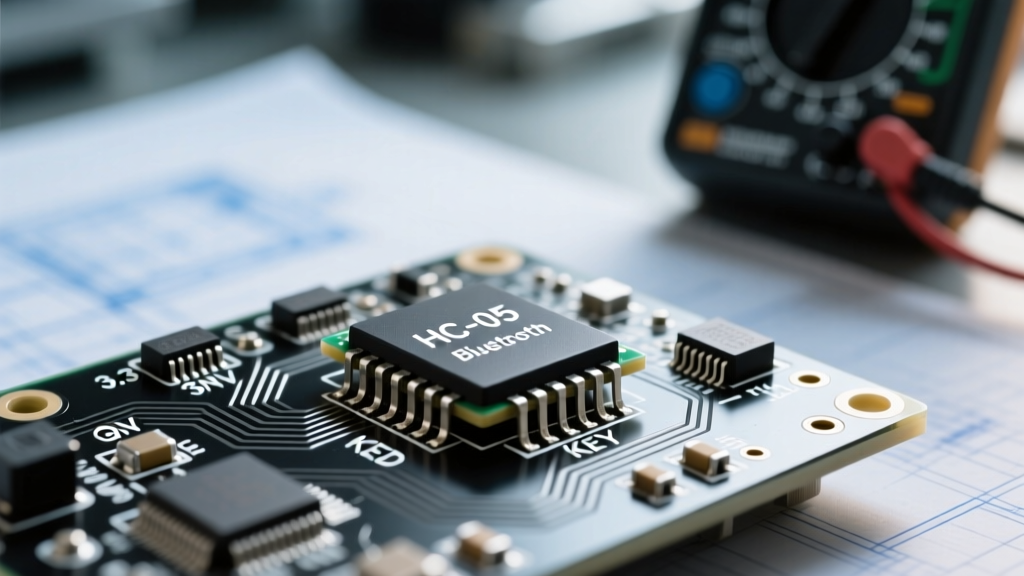
Bare HC-05 ICs are surface-mount and require complex RF antenna tuning. Therefore, 99% of hobbyists interact with the module via the ZS-040 breakout board. This board integrates the HC-05 core, a 26MHz crystal oscillator, an inverted-F PCB antenna, and crucially, a voltage regulator.
Understanding the ZS-040 schematic is vital for preventing hardware damage. Below is the definitive pinout for the standard 6-pin header found on these breakouts.
| Pin Label | Function | Voltage / Logic Level | Notes & Warnings |
|---|---|---|---|
| VCC | Power Input | 3.6V to 6V (Typically 5V) | Feeds the onboard MIC5205 LDO regulator. |
| GND | Ground | 0V | Must share a common ground with your MCU. |
| TXD | Transmit Data | 3.3V Logic HIGH | Outputs 3.3V. Safe to connect directly to 5V Arduino RX. |
| RXD | Receive Data | 3.3V Logic Tolerant | CRITICAL: Not 5V tolerant on most clones. Requires a voltage divider. |
| STATE | Connection Status | 3.3V Output | LOW = Disconnected, HIGH = Paired. Useful for MCU interrupts. |
| EN / KEY | Mode Select | 3.3V Input | Pull HIGH before power-on to enter AT Command Mode. |
The 3.3V Logic Level Trap
The most common point of failure for the HC-05 BT module is not a software bug, but a hardware oversight. The ZS-040 breakout board includes an LDO regulator that safely drops 5V from the VCC pin down to the 3.3V required by the internal HC-05 core. Because of this, beginners mistakenly assume the entire breakout board is 5V tolerant.
It is not. The RXD pin on the HC-05 silicon is strictly 3.3V tolerant. If you connect a 5V Arduino UNO TX pin directly to the HC-05 RXD pin, you will force 5V into a 3.3V logic gate. While some modules survive this abuse temporarily due to internal clamping diodes, it will inevitably lead to erratic data drops, overheating, and permanent silicon degradation.
The Fix: You must implement a simple resistive voltage divider on the RXD line. Connect a 1kΩ resistor in series between the Arduino TX and the HC-05 RXD. Then, connect a 2kΩ resistor from the HC-05 RXD to GND. This safely steps the 5V logic HIGH down to approximately 3.33V, protecting the module while ensuring reliable UART communication.
Mastering AT Command Mode
Out of the box, the HC-05 operates in Data Mode at a default baud rate of 9600 bps. To change the device name, alter the baud rate, or configure Master/Slave roles, you must force the module into AT Command Mode.
There is a widespread misconception about how to enter AT mode. Many tutorials suggest simply sending 'AT' via the serial monitor while the module is running. This will fail. The HC-05 determines its boot mode based on the state of the EN/KEY pin at the exact moment power is applied.
The Boot Sequence Procedure
- Wire the EN/KEY Pin: Connect the EN/KEY pin to a 3.3V source or an MCU GPIO pin set to HIGH. (If your ZS-040 board has a tiny tactile button, this button is internally wired to the EN pin via a trace).
- Apply Power: With the EN pin held HIGH, apply power to the VCC and GND pins.
- Observe the LED: The onboard LED should blink slowly (approximately 1 second ON, 1 second OFF). This slow pulse confirms you are in AT mode.
- Set Serial Baud Rate: Open your Serial Monitor and set the baud rate to 38400. The HC-05 defaults to 38400 bps for AT commands, regardless of its Data Mode baud rate.
- Line Endings: Ensure your Serial Monitor is set to append Both NL & CR (Carriage Return and Line Feed). The HC-05 firmware requires the '\r\n' characters to parse the end of a command string.
Essential AT Commands for Configuration
Once in AT mode, you can query and write to the module's non-volatile memory. Below are the most critical commands for real-world deployments.
| Command | Description | Expected Response | Use Case |
|---|---|---|---|
| AT | Test connection | OK | Verify Serial Monitor wiring and baud rate. |
| AT+NAME=MyDevice | Change Bluetooth name | OK | Identify your device in crowded RF environments. |
| AT+PSWD=1234 | Change pairing PIN | OK | Secure the module against unauthorized pairing. |
| AT+UART=115200,0,0 | Change Data Mode baud rate | OK | Match high-speed MCU logging requirements. |
| AT+ROLE=1 | Set as Master | OK | Required if the HC-05 must initiate connections. |
| AT+BIND=98d3,34,21c | Bind to specific MAC | OK | Auto-connect to a specific Slave device on boot. |
Master vs. Slave Architecture
Unlike the HC-06, which is permanently hardcoded as a Slave device, the HC-05 BT module can act as either a Master or a Slave. This distinction is fundamental when designing sensor networks or telemetry links.
In Slave Mode (AT+ROLE=0), the module waits passively for a central device (like a smartphone or a Master HC-05) to initiate a pairing request. This is ideal for data loggers that upload to a PC.
In Master Mode (AT+ROLE=1), the HC-05 actively scans the 2.4GHz spectrum for other Bluetooth devices. By using the AT+CMODE=0 (fixed address mode) and AT+BIND commands, you can configure a Master HC-05 to automatically seek out and connect to a specific Slave HC-05 the moment power is applied, creating a seamless, wireless serial bridge without any user intervention or smartphone pairing menus.
Pro-Tip from the Bench: When configuring a Master-Slave pair, always configure the Slave first. Note its MAC address using the
AT+ADDR?command. Then, input that exact address (using commas instead of colons) into the Master'sAT+BINDparameter. Forgetting to swap colons for commas is the #1 reason for 'ERROR: (17)' syntax failures.
Real-World Troubleshooting & Failure Modes
Even with perfect wiring, RF environments and power delivery issues can cause headaches. Here is how to diagnose the most common HC-05 failure modes using a multimeter and logical deduction.
1. The 'Rapid Blink' but No Data
If the LED is blinking rapidly (approx. 5 times per second), the module is in Data Mode and waiting to pair. If your smartphone sees the device but fails to pair, or pairs but drops immediately, you are likely experiencing a current starvation issue. During the initial handshake and encryption phase, the HC-05 can draw current spikes up to 150mA. If you are powering the module from an Arduino's onboard 5V regulator that is already heavily loaded, the voltage will sag, causing the HC-05's internal baseband processor to brownout and reset. Solution: Power the HC-05 VCC pin from a dedicated external buck converter or a high-current USB power bank.
2. AT Command Timeouts
If you send 'AT' and receive nothing, verify your logic levels. Use a digital multimeter to probe the TXD pin of the HC-05 while in AT mode. You should see it pulsing or sitting at 3.3V. If it sits at 0V, the module may be stuck in a crashed state due to a corrupted EEPROM byte. A hard factory reset can sometimes be triggered by holding the EN pin HIGH, applying power, and sending AT+ORGL (Restore Original Settings) blindly, hoping the baud rate matches.
3. Garbage Characters in the Serial Monitor
If you receive hieroglyphics instead of 'OK', your baud rates are mismatched. While 38400 is the standard AT mode baud rate for genuine CSR-based HC-05 modules, some ultra-cheap clone firmware defaults to 9600 bps even in AT mode. Cycle through 9600, 19200, and 38400 in your Serial Monitor until the 'OK' response appears cleanly.
References and Further Reading
For those looking to dive deeper into the CSR BC417 AT command set and advanced RF tuning, the following resources are considered the gold standard in the electronics community:
- Martyn Currey's HC-05 Slave Mode Guide - An exhaustive, multi-part series detailing every known AT command, firmware variation, and edge case for the HC-05 and HC-06 modules.
- Components101 HC-05 Datasheet & Pinout - Excellent reference for baseline electrical characteristics, maximum ratings, and standard SPP profile behaviors.
By respecting the 3.3V logic boundaries and mastering the boot-sequence requirements of AT mode, the HC-05 BT module transforms from a frustrating black box into a highly reliable, versatile tool for your wireless electronics arsenal.