
Integrating a GPS module into a microcontroller project is a rite of passage for electronics enthusiasts, drone builders, and IoT engineers. However, moving beyond simply plugging in a breakout board requires a deep understanding of RF hardware, serial communication protocols, and satellite constellation physics. Whether you are building a high-altitude balloon tracker or a low-power asset logger, mastering the fundamentals of GPS hardware and NMEA data parsing is critical for reliable operation.
The Anatomy of a Standard GPS Module
A typical GPS breakout board is not just a single chip; it is a carefully tuned RF front-end paired with a digital baseband processor. Understanding these components helps explain why certain modules fail in specific environments.
Ceramic Patch Antenna and SAW Filter
The large square ceramic element on top of most modules is a patch antenna tuned to the L1 GPS frequency (1575.42 MHz). Because GPS signals arriving at Earth's surface are incredibly weak (often around -130 dBm, which is below the thermal noise floor), the signal must be filtered and amplified immediately. The signal passes through a Surface Acoustic Wave (SAW) filter to reject out-of-band interference (like nearby cellular towers) before entering the Low Noise Amplifier (LNA). If you are designing a custom PCB, keeping the RF trace between the antenna and the module's RF_IN pin as short and impedance-matched (usually 50 ohms) as possible is non-negotiable.
Decoding the Matrix: NMEA 0183 Sentences
Most GPS modules communicate with host microcontrollers via UART using the NMEA 0183 standard. NMEA (National Marine Electronics Association) outputs human-readable ASCII sentences. While modern modules also support binary protocols (like u-blox's UBX), NMEA remains the universal baseline.
$GPRMC,123519,A,4807.038,N,01131.000,E,022.4,084.4,230394,003.1,W*6A
Breaking Down the $GPRMC Sentence
The Recommended Minimum Specific GNSS Data ($GPRMC or $GNRMC) is the most efficient sentence for basic tracking. Let us dissect the fields:
- $GPRMC: Sentence header (Global Positioning, Recommended Minimum).
- 123519: UTC time (12:35:19).
- A: Status (A = Active/Valid, V = Void/No Lock).
- 4807.038,N: Latitude (48 degrees, 07.038 minutes North).
- 01131.000,E: Longitude (11 degrees, 31.000 minutes East).
- 022.4: Speed over ground in knots.
- 084.4: Track angle in degrees (True).
- 230394: Date (23rd March 1994).
- *6A: Checksum (XOR of all characters between $ and *).
Pro Tip: Always validate the XOR checksum in your C++ or Python parsing routines. RF interference and UART buffer overruns frequently corrupt serial data, and relying on unverified NMEA strings will result in phantom coordinates.
Hardware Integration: Wiring to Microcontrollers
The most common point of failure for beginners is improper UART wiring and logic level mismatching. GPS modules transmit data continuously, meaning the microcontroller must use Hardware Serial or high-performance Software Serial to avoid dropping bytes.
The UART Crossover Rule and Logic Levels
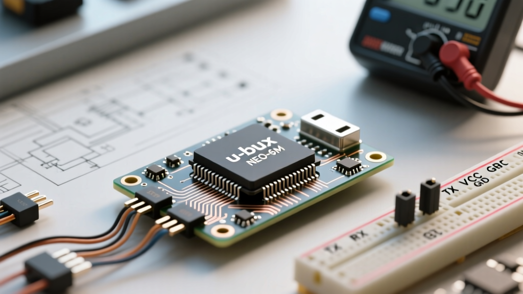
UART communication requires a crossover connection: the TX (Transmit) pin of the GPS must connect to the RX (Receive) pin of the microcontroller, and vice versa. Furthermore, modern high-performance GPS chips operate strictly at 3.3V logic levels. Connecting a 5V Arduino Uno TX pin directly to a 3.3V GPS RX pin can permanently destroy the module's silicon. Always use a logic level shifter or a voltage divider (e.g., 2kΩ and 3.3kΩ resistors) when interfacing with 5V boards.
| GPS Module Pin | Arduino Uno (5V) | ESP32 (3.3V) | Notes |
|---|---|---|---|
| VCC | 5V (if breakout has regulator) | 3.3V | Check breakout board schematic first |
| GND | GND | GND | Common ground is mandatory |
| TX | Digital Pin 10 (SoftSerial RX) | GPIO 16 (Hardware RX2) | GPS TX sends data TO MCU RX |
| RX | Voltage Divider to Pin 11 | GPIO 17 (Hardware TX2) | MCU TX sends commands TO GPS RX |
Chipset Showdown: NEO-6M vs. M8N vs. M10S
Choosing the right silicon is heavily dependent on your power budget and environmental constraints. The market is dominated by u-blox chipsets, each serving a distinct engineering niche. According to the u-blox M10S product documentation, modern architectures have shifted drastically from legacy designs.
| Feature | u-blox NEO-6M | u-blox NEO-M8N | u-blox MAX-M10S |
|---|---|---|---|
| Generation | Legacy (Gen 6) | Standard (Gen 8) | Modern (Gen 10) |
| Concurrent GNSS | 1 (GPS only) | 2 (e.g., GPS + GLONASS) | 4 (GPS, GLONASS, Galileo, BeiDou) |
| Channels | 50 | 72 | 92 |
| Tracking Current | ~45 mA | ~33 mA | ~12 mA |
| Best Use Case | Basic hobbyist projects | Drones, automotive, high-dynamic | Battery-powered IoT, wearables |
If you are building a solar-powered wildlife tracker, the MAX-M10S is mandatory due to its 12 mA tracking current and ability to lock onto four constellations simultaneously under heavy tree canopy. For FPV racing drones, the NEO-M8N remains the gold standard due to its high dynamic performance and robust 5Hz+ update rates.
Troubleshooting TTFF (Time to First Fix)
Time to First Fix (TTFF) is the duration between powering on the module and achieving a valid 3D coordinate lock. A comprehensive guide by SparkFun highlights that TTFF is heavily dependent on the availability of orbital data (Ephemeris and Almanac).
Cold Start vs. Warm Start Realities
- Cold Start (25-30 minutes): The module has no stored orbital data. It must download the Almanac (coarse orbits for all satellites) and Ephemeris (precise orbits for visible satellites) directly from the satellites at a sluggish 50 bits per second. This requires a clear, unobstructed view of the sky.
- Warm Start (1-5 minutes): The module has valid Almanac data and an approximate time/location. It only needs to download the Ephemeris for the specific satellites currently above the horizon.
- Hot Start (< 1 second): The module knows exactly which satellites to look for and their precise Doppler shifts, allowing immediate lock.
The V_BATT Backup Pin
To achieve warm or hot starts, the GPS module's internal Real-Time Clock (RTC) and SRAM must remain powered when the main VCC is cut. Most breakout boards expose a V_BATT or VBAT pin. By connecting this to a 3V CR1220 coin cell or a supercapacitor, the module retains its ephemeris data for weeks. If your project requires rapid TTFF upon waking from deep sleep, never leave the V_BATT pin floating.
Final Integration Advice
When debugging a GPS module that refuses to lock, isolate the variables. First, verify the baud rate (default is almost always 9600 bps for NMEA). Second, ensure you are testing outdoors; modern architectural materials and energy-efficient window coatings act as Faraday cages that block L-band RF signals entirely. Finally, utilize software tools like u-center (for u-blox chips) to visualize the signal-to-noise ratio (SNR) of individual satellites, allowing you to diagnose antenna placement issues before deploying your hardware into the field.