
The Anatomy of the 40-Pin Header: Beyond the Basic RPi GPIO Pin Diagram
When makers and engineers search for an rpi gpio pin diagram, they are usually staring at a tangled mess of jumper wires, a non-responsive sensor, or worse, a Raspberry Pi that refuses to boot. The standard 40-pin header on the Raspberry Pi 3, 4, and 5 is a marvel of single-board computing, but it lacks the physical silkscreen labeling found on most Arduino MCUs. This absence of onboard documentation turns the digital pinout diagram into your primary troubleshooting map.
Before diagnosing hardware faults, you must resolve the most common software-to-hardware mapping error: BOARD vs. BCM numbering. The physical pin diagram uses BOARD numbering (1 through 40, reading left-to-right, top-to-bottom with the USB ports facing you). However, Broadcom SoC documentation and libraries like Python's RPi.GPIO default to BCM numbering. For example, physical Pin 3 is BCM 2 (SDA1). If your code targets BCM 3 but you wire to physical Pin 3, your I2C bus will fail silently. Always cross-reference your software library's numbering scheme against the physical diagram before applying power.
Diagnostic Matrix: Mapping Symptoms to Specific GPIO Pins
Use this troubleshooting matrix to isolate failures based on your project's symptoms. This framework assumes you are using a standard Raspberry Pi 4 or 5 running Raspberry Pi OS.
| Symptom | Suspect Pins (BOARD / BCM) | Root Cause | Hardware / Software Fix |
|---|---|---|---|
| I2C sensor not detected | Pins 3 & 5 / BCM 2 & 3 | Missing pull-up resistors or 5V logic clash | Add 4.7kΩ pull-ups to 3.3V; use TXS0108E level shifter |
| UART serial garbage data | Pins 8 & 10 / BCM 14 & 15 | Bluetooth mini-UART conflict or baud mismatch | Add dtoverlay=disable-bt to config.txt |
| Pi reboots under load | Pins 2 & 4 (5V Power) | Voltage drop via thin jumper wires | Use 22 AWG wire or power via USB-C / PoE HAT |
| GPIO reads constant HIGH | Any GPIO (e.g., Pin 11 / BCM 17) | Floating input pin lacking ground reference | Enable internal pull-down in software or add 10kΩ external resistor |
Scenario A: The "Dead" I2C Sensor Bus (Pins 3 & 5)
The I2C bus (SDA on Pin 3, SCL on Pin 5) is the backbone of maker sensor integration. A frequent failure mode occurs when running i2cdetect -y 1 yields a blank grid or hangs the terminal. According to the official Raspberry Pi documentation, the Pi includes 1.8kΩ onboard pull-up resistors to 3.3V on these specific pins. However, if you are wiring long cables or daisy-chaining multiple sensors, the bus capacitance increases, degrading the signal edges.
The Fix: Add external 4.7kΩ pull-up resistors to the 3.3V rail (Pin 1). Furthermore, if you are interfacing a 5V Arduino-compatible module (like an older HC-SR04 or certain LCD backpacks), you are risking back-voltage into the Pi's 3.3V SoC. You must route Pins 3 and 5 through a bidirectional logic level shifter, such as the Adafruit TXS0108E, referencing the low-voltage side to Pin 1 and the high-voltage side to a 5V rail (Pin 2).
Scenario B: UART Serial Console Garbage (Pins 8 & 10)
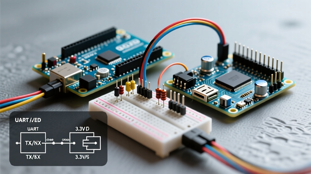
Wiring a GPS module or an Arduino to the Pi's UART (TX on Pin 8, RX on Pin 10) often results in corrupted, unreadable characters. On the Pi 3 and 4, the primary hardware UART (PL011) is routed to the Bluetooth module, leaving the less stable "mini-UART" mapped to the GPIO header. The mini-UART derives its baud rate from the core clock, which fluctuates with CPU load, causing data corruption.
The Fix: You must force the PL011 UART back to the GPIO pins by disabling Bluetooth. Open /boot/firmware/config.txt (or /boot/config.txt on older OS versions) and append dtoverlay=disable-bt. Reboot, and verify the mapping using ls -l /dev/serial*. Ensure your hardware TX connects to the Pi's RX (Pin 10), and hardware RX to the Pi's TX (Pin 8).
Multimeter Testing Protocol for Suspected Dead Pins
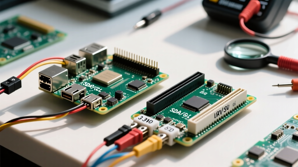
If you have accidentally fed 5V into a 3.3V BCM GPIO pin, you may have permanently damaged the SoC's IO bank. Before declaring the board dead, execute this strict multimeter protocol to verify the physical layer. Warning: Never backpower the Pi via the 5V GPIO pins while the USB-C power supply is also connected, as this bypasses the onboard protection circuitry and can cause catastrophic thermal failure.
- Continuity Test (Power Off): Set your multimeter to continuity. Place the black probe on a known ground (e.g., Pin 6) and the red probe on the suspected ground pin. A beep confirms the ground plane is intact.
- Voltage Rail Verification (Power On): Set to DC Voltage. Measure between Pin 1 (3.3V) and Pin 6 (GND). It must read 3.28V to 3.33V. Measure Pin 2 (5V) to Pin 6. It must read 4.95V to 5.10V. If the 3.3V rail reads near 0V, the onboard polyfuse or the SoC's internal voltage regulator has failed.
- GPIO Toggle Test: Write a simple Python script using the
gpiozerolibrary to toggle a suspect pin HIGH and LOW every 1 second. Set the multimeter to DC Voltage and probe the pin. A healthy pin will swing between ~0.05V and ~3.25V. If it remains stuck at 0V or 3.3V regardless of software state, the GPIO pad is physically burned out.
The Raspberry Pi 5 Paradigm Shift: RP1 and Pinctrl
Troubleshooting the rpi gpio pin diagram on the Raspberry Pi 5 requires a fundamental shift in understanding. Unlike the Pi 4, which routed GPIO directly from the Broadcom BCM2711 SoC, the Pi 5 offloads all GPIO, I2C, SPI, and UART functions to a custom RP1 southbridge chip.
This architectural change means legacy troubleshooting tools like wiringPi or raspi-gpio are entirely obsolete and will return errors or false data. To troubleshoot pin states on a Pi 5, you must use the pinctrl utility. Running pinctrl get will dump the exact state, drive strength, and pull-up/pull-down configuration of all 40 pins as managed by the RP1 chip. The RP1 allows for configurable drive strengths up to 12mA per pin, which is crucial when driving small LED arrays without external transistors. If a pin is misbehaving, use pinctrl set 17 pn to manually clear pull resistors, or pinctrl set 17 pu to force a pull-up, isolating whether the fault lies in your Python code or the physical wiring.
Preventative Frameworks for Future Maker Projects
The most catastrophic failure mode associated with the RPi GPIO pin diagram is the "shifted-by-one" ribbon cable error. If a 40-pin GPIO ribbon cable is plugged in offset by a single row, Pin 2 (5V) is routed directly into Pin 3 (BCM 2 / SDA), instantly frying the I2C controller and potentially the entire SoC.
Expert Rule of Thumb: Never connect or disconnect ribbon cables while the Pi is powered via USB-C. Always use a keyed GPIO breakout board (like the Pi Cobbler) that physically prevents misalignment, and verify the red stripe on your ribbon cable aligns with Pin 1 (the 3.3V corner) before applying power.
By treating the pinout diagram not just as a reference, but as a diagnostic schematic, you can systematically isolate I2C capacitance issues, UART clock drift, and logic-level mismatches. Cross-referencing physical wiring with tools like Pinout.xyz ensures your mental model matches the silicon. Master these troubleshooting vectors, and your Raspberry Pi will serve as a reliable bridge between high-level computing and low-level MCU electronics.