
The ESP8266 Audio Bottleneck: Why Most Microphones Fail
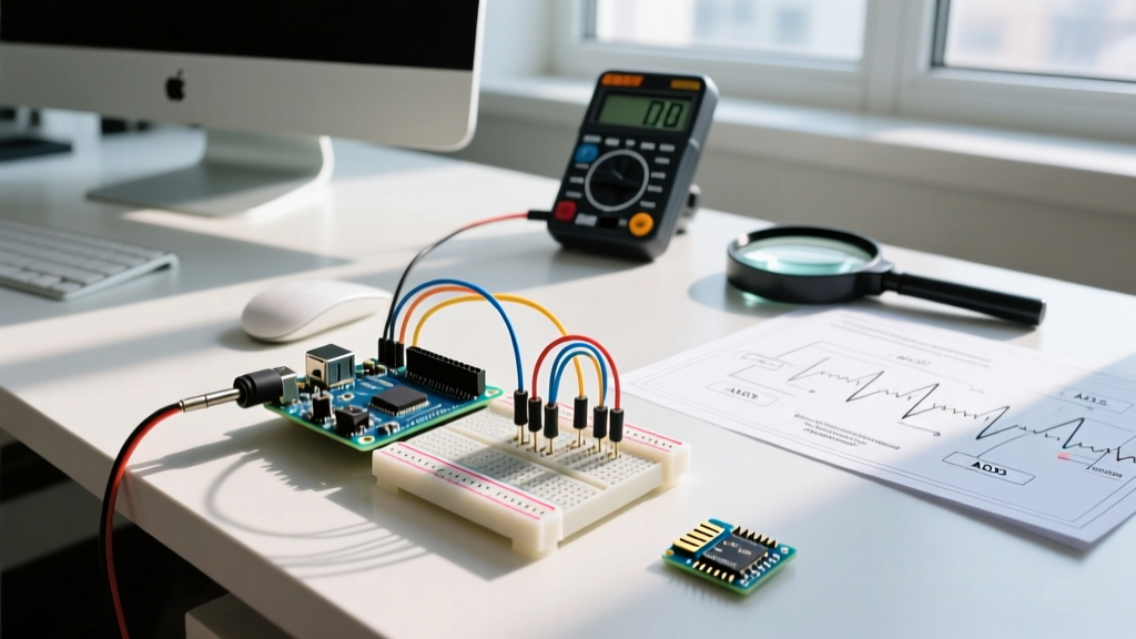
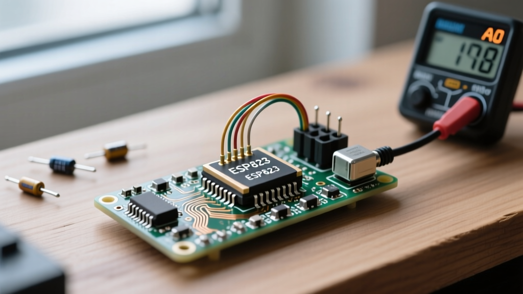
Integrating an esp8266 microphone input into a maker project is a notorious rite of passage that often ends in frustration. Unlike its successor, the ESP32, the ESP8266 lacks a native I2S (Inter-IC Sound) input peripheral. This architectural limitation means you cannot simply wire up modern digital MEMS microphones like the INMP441 or ICS-43434 and expect to capture high-fidelity audio. Instead, you are forced to rely on the chip's single analog-to-digital converter (ADC) pin, typically labeled as A0 or TOUT.
According to the Espressif ESP8266 Hardware Design Guidelines, the TOUT pin is a 10-bit SAR ADC. However, the voltage tolerance is where most makers destroy their boards or clip their audio signals. The raw ESP8266EX chip accepts an input voltage range of 0V to 1.0V. If you feed a 3.3V audio signal directly into a raw ESP-12F module, you will not only clip the audio waveform into a distorted square wave, but you also risk damaging the silicon over time.
Development boards like the NodeMCU v3 and Wemos D1 Mini include an onboard resistor voltage divider (usually 220kΩ and 100kΩ) that scales the 0-3.3V input down to the 0-1.0V range the chip requires. Understanding which board you are using is the absolute first step in designing a compatible microphone circuit.
Microphone Module Compatibility Matrix
Not all microphone modules are created equal. Below is a compatibility matrix detailing which modules work with the ESP8266 and what limitations you will face.
| Module | Type | Interface | ESP8266 Compatibility | Use Case |
|---|---|---|---|---|
| MAX9814 | Electret Amp | Analog | ✅ Compatible (Requires Voltage Matching) | Voice recording, FFT analysis |
| KY-038 | Electret + LM393 | Analog / Digital | ⚠️ Limited (Threshold only) | Clap detection, sound alarms |
| INMP441 | MEMS | I2S | ❌ Incompatible (No I2S Input) | N/A (Use ESP32 instead) |
| SPH0645LM4H | MEMS PDM | I2S / PDM | ❌ Incompatible | N/A (Use ESP32 instead) |
As the table illustrates, the MAX9814 is the undisputed champion for ESP8266 audio projects. It features an Automatic Gain Control (AGC) circuit and a low-noise microphone bias amplifier, making it capable of outputting a clean analog waveform that the ESP8266's ADC can sample.
Wiring the MAX9814 to the ESP8266 A0 Pin
The Analog Devices MAX9814 outputs a biased analog signal. The audio waveform oscillates around a DC bias voltage of approximately 1.25V. With a maximum peak-to-peak swing of roughly 2V, the absolute maximum voltage hitting the output pin can reach 2.25V.
Calculating the Voltage Divider for Raw ESP-12 Modules
If you are using a raw ESP-12E or ESP-12F module (where A0 maxes out at 1.0V), you must build a voltage divider to scale the MAX9814's 2.25V peak down to 1.0V.
- Target Ratio: 1.0V / 2.25V ≈ 0.44
- Resistor R1 (Series): 12kΩ
- Resistor R2 (Ground): 10kΩ
- Formula: Vout = Vin * (R2 / (R1 + R2))
- Result: 2.25V * (10 / 22) = 1.02V (Safe for the 1.0V limit)
If you are using a NodeMCU or Wemos D1 Mini, the onboard divider handles the 3.3V scaling. You can wire the MAX9814 OUT pin directly to the A0 pin on the development board, as the 2.25V peak is well within the 3.3V tolerance of the board's input trace.
Configuring the AGC and Gain Pins
The MAX9814 features a MICGAIN pin that allows you to set the amplification level. This is critical for optimizing the signal-to-noise ratio (SNR) before the signal even reaches the ESP8266.
- 60dB Gain: Connect MICGAIN to GND. Best for distant sound sources or quiet rooms.
- 50dB Gain: Leave MICGAIN floating (unconnected). The default setting for general-purpose voice.
- 40dB Gain: Connect MICGAIN to VDD (3.3V). Best for loud environments or when the mic is placed directly next to the speaker's mouth.
Expert Tip: The ESP8266's 10-bit ADC yields only 1024 discrete steps. If your audio signal only swings between 400 and 600 on the ADC scale due to low gain, you are capturing less than 2 bits of effective audio resolution. Always maximize the analog gain at the MAX9814 stage so the waveform spans from ADC value 100 to 900, utilizing the full dynamic range of the chip.
Software Sampling Limits: analogRead vs. Timer Interrupts
Capturing audio is fundamentally a race against time. To capture human voice intelligibly, you need a minimum sampling rate of 8,000 Hz (8kHz), according to the Nyquist-Shannon sampling theorem. This means you must read the ADC pin every 125 microseconds.
The standard Arduino analogRead(A0) function on the ESP8266 takes approximately 70 to 100 microseconds to execute. While this theoretically allows for 10kHz sampling, it is a blocking function. Furthermore, the ESP8266's Wi-Fi stack operates via background interrupts. When the radio transmits or receives a packet, it halts your main loop for 1 to 5 milliseconds. If you rely on a simple while loop or delayMicroseconds() to sample audio, Wi-Fi interrupts will cause massive timing jitter, resulting in robotic, garbled, or completely dropped audio frames.
The Hardware Timer Solution
To achieve a stable esp8266 microphone input stream while maintaining Wi-Fi connectivity, you must offload the ADC reading to a hardware timer interrupt. The ESP8266 Arduino Core provides access to Timer1.
By attaching an interrupt service routine (ISR) to Timer1, you can force the chip to read the ADC exactly every 125µs, store the value in a circular buffer array, and set a flag. Your main loop() then watches for this flag and processes the buffer (e.g., sending it over WebSockets or running an FFT) without disrupting the sampling clock.
For a deeper dive into the ESP8266 ADC architecture and timer registers, consult the ESP8266 Arduino Core ADC Documentation on GitHub, which outlines the underlying Non-OS SDK limitations regarding ADC reads during RF transmission events.
Combating EMI and Wi-Fi Ground Bounce
The ESP8266 is a 2.4GHz RF powerhouse. When the antenna transmits, it draws sudden spikes of current (up to 170mA) from the power rail. This causes "ground bounce" and injects high-frequency electromagnetic interference (EMI) directly into the analog traces. If your microphone wiring is not properly isolated, your audio output will feature a distinct, rhythmic buzzing sound synced to your Wi-Fi beacon intervals.
Hardware Mitigation Strategies:
- Decoupling Capacitors: Place a 100nF ceramic capacitor and a 10µF tantalum capacitor as physically close to the MAX9814 VCC and GND pins as possible. This creates a local energy reservoir that prevents Wi-Fi TX spikes from starving the mic amplifier.
- Trace Routing: Keep the analog trace from the MAX9814 OUT pin to the ESP8266 A0 pin as short as possible. Do not route this trace parallel to the ESP8266 antenna or the main 3.3V power lines.
- Software Averaging: If you are only measuring ambient noise levels (dB SPL) rather than streaming raw audio, take 64 rapid samples in the ISR, average them, and discard the high-frequency RF noise artifacts.
When to Abandon the ESP8266 for Audio Projects
While mastering the esp8266 microphone input via the A0 pin and MAX9814 is an excellent exercise in embedded systems engineering, it has a hard ceiling. You are limited to narrowband voice quality (8kHz - 16kHz mono). You cannot achieve high-fidelity 44.1kHz stereo audio, and the CPU overhead of managing ADC interrupts alongside TLS-encrypted MQTT or HTTP requests will frequently trigger the ESP8266's hardware watchdog timer (WDT), causing random reboots.
If your project requires wake-word detection, high-quality audio streaming to a cloud API, or I2S digital MEMS microphones, it is time to upgrade to the ESP32. The ESP32 features dual I2S peripherals, a 12-bit ADC, and a dual-core processor that dedicates Core 0 entirely to Wi-Fi/Bluetooth while Core 1 handles uninterrupted audio DSP tasks. However, for simple sound-triggered relays, basic voice note recording, or FFT-based frequency analysis, the ESP8266 and MAX9814 remain a highly cost-effective and capable pairing.