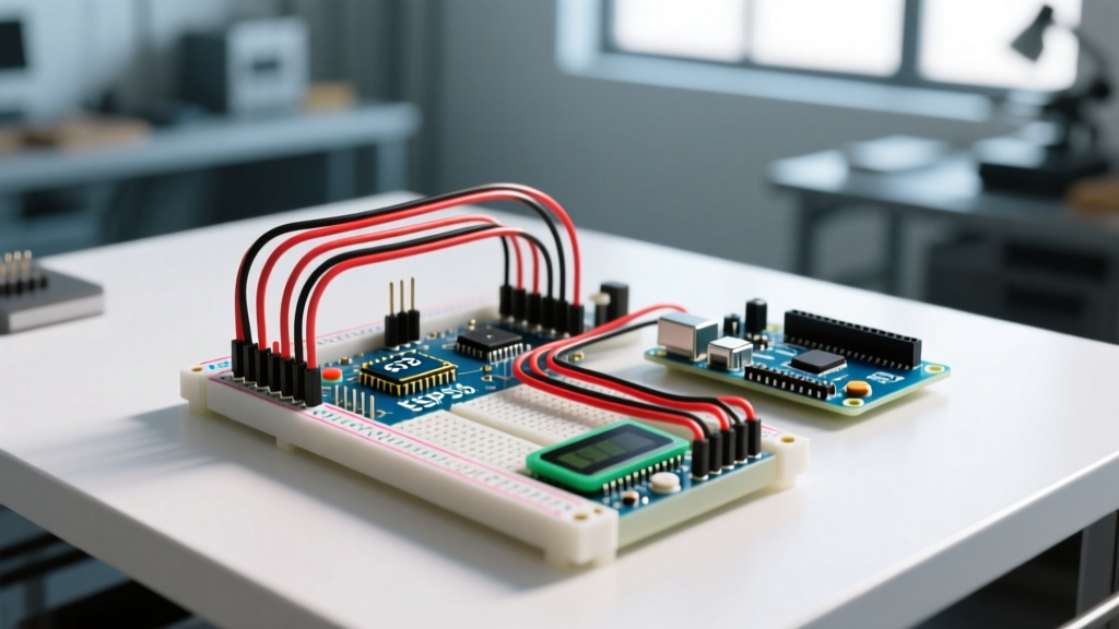

When transitioning from theoretical circuit design to physical prototyping, the Arduino breadboard remains the most critical tool in a maker's arsenal. Whether you are testing a simple LED blink sketch on an Arduino Uno R4 Minima or wiring up a complex I2C sensor array on a Nano ESP32, a solderless breadboard allows for rapid iteration without the permanence of solder. However, beneath the seemingly simple grid of plastic holes lies a complex network of metal spring clips, hidden discontinuities, and electrical quirks that can derail your project if misunderstood.
In this comprehensive concept explainer, we will deconstruct the internal anatomy of the breadboard, expose the infamous "split-rail" trap, analyze signal integrity limitations, and provide a step-by-step wiring framework for your next microcontroller build.
The Internal Anatomy of a Solderless Breadboard
To wire an Arduino breadboard effectively, you must first visualize what is happening beneath the plastic housing. As detailed in SparkFun's comprehensive breadboard guide, the board is composed of three primary internal structures:
- Terminal Strips (The Main Grid): The central area of the board is divided into rows of five holes (typically labeled A-E and F-J). Beneath each row of five sits a single phosphor bronze leaf-spring clip. When you insert a component lead or jumper wire, the metal clip grips it, electrically connecting all five holes in that specific row.
- The DIP Ravine (Center Trench): The physical groove running down the exact center of the board serves two purposes. First, it provides physical clearance for Dual In-line Package (DIP) integrated circuits to straddle the gap. Second, it ensures that the top terminal strips (A-E) and bottom terminal strips (F-J) are completely isolated from one another, preventing short circuits across IC pins.
- Bus Strips (Power Rails): Running horizontally along the top and bottom edges (usually marked with red and blue lines) are the power rails. Unlike the terminal strips, these are connected horizontally in long continuous strips designed to distribute 5V, 3.3V, and GND across the entire length of the board.
The 830-Point "Split-Rail" Trap
One of the most common failure modes for beginners working with an Arduino breadboard—specifically the popular 830-tie-point full-size models costing around $6 to $8 in 2026—is the split power rail. On many generic 830-point breadboards, the long horizontal bus strips are not a single continuous piece of metal. Instead, they are split into two halves (left and right) with a physical gap in the middle.
⚠️ Pro-Tip: The Split-Rail Test
Before wiring your Arduino, always test your power rails with a multimeter's continuity beep mode. If you plug 5V into the far-left red rail, the far-right red rail might remain completely dead. To fix this, you must run a dedicated jumper wire bridging the left and right halves of the red and blue rails to ensure uniform power distribution across your entire circuit.
Signal Integrity: Parasitic Capacitance and High-Frequency Limits
While breadboards are perfect for basic digital I/O and low-speed analog reads, they introduce a hidden enemy to high-speed microcontroller protocols: parasitic capacitance. Every time a wire or component lead touches the internal metal leaf spring, it introduces roughly 2pF to 5pF (picofarads) of stray capacitance into the circuit.
For standard GPIO operations or reading a pushbutton, this is negligible. However, if you are routing high-speed SPI lines (e.g., communicating with an SD card module or a high-resolution TFT display at clock speeds above 4MHz), this accumulated capacitance can round off the sharp edges of your digital square waves. This leads to data corruption and failed handshakes. For high-speed MCU peripherals, keep jumper wires as short as physically possible (under 2 inches) or transition to a custom PCB or perfboard.
Selecting the Right Jumper Wires for MCU Prototyping
The physical connection between your Arduino and the breadboard relies entirely on the quality of your jumper wires. Using the wrong wire gauge or type will result in intermittent connections, damaged breadboard contacts, or frustrating debugging sessions.
| Wire Type | AWG Size | Pros | Cons | Best Use Case |
|---|---|---|---|---|
| Solid Core | 22 AWG | Perfect fit for standard 0.1" breadboard holes; holds shape; excellent contact pressure. | Can snap if bent repeatedly at the same stress point. | Standard Arduino breadboard wiring, component leads. |
| Solid Core (Thin) | 24 AWG | More flexible; easier to route in tight spaces. | Can cause poor contact in older, worn-out breadboard springs. | Dense DIP IC wiring, tight jumper routing. |
| Stranded Core | 22-26 AWG | Highly flexible; will not break from bending. | Strands splay out, ruining breadboard contacts and causing shorts. | Never use raw stranded wire in a solderless breadboard. |
| Pre-formed Kits | Varies | Pre-cut and pre-bent for flat, organized layouts. | Can be difficult to remove; limits custom routing heights. | Complex, permanent-ish breadboard prototypes. |
Step-by-Step: Wiring a Button and LED on an Arduino Breadboard
Let's apply this knowledge to a foundational circuit: reading a pushbutton to toggle an LED. This setup requires understanding both power distribution and digital pin configuration, as outlined in the official Arduino digital pins documentation.
- Establish Power Rails: Connect a jumper from the Arduino Uno R4
5Vpin to the left-side red bus strip. Connect the ArduinoGNDpin to the left-side blue bus strip. (Remember to bridge the rails if using an 830-point board). - Place the Pushbutton: Straddle the center DIP ravine with a standard 6x6mm tactile switch. Ensure the pins rest in the terminal strips (e.g., pins on row 10 and row 12).
- Wire the LED: Insert the anode (long leg) of a 5mm LED into row 20, column A. Insert the cathode (short leg) into the blue GND rail. Always use a current-limiting resistor (220Ω to 330Ω) in series with the anode to prevent burning out the LED or overloading the Arduino GPIO pin.
- Configure the Pull-Up Resistor: Instead of wiring an external 10kΩ pull-down resistor to GND, utilize the microcontroller's internal architecture. Connect one side of the button directly to Arduino Digital Pin 2, and the other side to GND. In your sketch, initialize the pin using
pinMode(2, INPUT_PULLUP);. This activates the internal 20kΩ-50kΩ resistor, keeping the pin HIGH until the button bridges it to GND (reading LOW).
Troubleshooting Matrix: Common Breadboard Failures
Even experienced engineers encounter phantom bugs when prototyping. Use this matrix to diagnose erratic behavior in your Arduino breadboard setups.
| Symptom | Likely Cause | Actionable Fix |
|---|---|---|
| LED glows dimly or flickers randomly | Floating pin or missing common ground. | Ensure the Arduino GND and breadboard GND rail share a physical connection. Check for loose 24 AWG wires. |
| Right side of the board is completely dead | The 830-point split-rail trap. | Run a jumper wire across the center gap of the red and blue power rails. |
| Sensor readings are erratic/noisy | Long jumper wires acting as antennas, or breadboard contact resistance. | Shorten wire lengths. Add a 0.1µF ceramic decoupling capacitor directly across the sensor's VCC and GND pins on the breadboard. |
| Arduino resets when motor/relay triggers | Voltage brownout caused by shared power rails. | Never power inductive loads directly from the Arduino 5V rail. Use an external power supply and a logic-level MOSFET, sharing only the GND rail. |
Conclusion
Mastering the Arduino breadboard is about more than just pushing wires into plastic holes. It requires an understanding of internal connectivity, an awareness of parasitic electrical properties, and strict adherence to wire gauge standards. By avoiding the split-rail trap, leveraging internal pull-up resistors to reduce clutter, and respecting the physical limits of solderless contacts, you can transform your breadboard from a source of frustrating bugs into a reliable foundation for your 2026 microcontroller projects.