
Introduction: Why the ESP32-WROOM-32 Pinout Trips Up Makers
The ESP32-WROOM-32 is arguably the most popular Wi-Fi and Bluetooth module in the maker community. Powered by the dual-core Tensilica LX6 microcontroller (specifically the ESP32-D0WDQ6 chip), it offers immense processing power at a fraction of the cost of traditional alternatives. However, its sheer capability comes with a complex hardware architecture. If you have ever wired a sensor only to find your board stuck in a boot loop, or watched your analog readings turn to garbage the moment Wi-Fi connects, you have fallen victim to the quirks of the esp32-wroom-32 pinout.
Unlike the straightforward Arduino Uno, the ESP32 multiplexes its 34 programmable GPIO pins across multiple internal peripherals. This tutorial provides a rigorous, step-by-step framework for mapping, wiring, and troubleshooting your ESP32-WROOM-32 dev board to ensure rock-solid reliability in your DIY electronics projects.
Step 1: Decoding the Physical Layout and Module Constraints
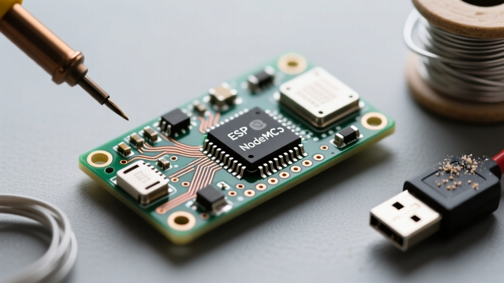
Before writing a single line of code, you must understand the physical hardware. The raw ESP32-WROOM-32 module features 38 pins, but the metal shielding and internal flash routing make several of these inaccessible or strictly reserved. When you buy a standard 'DevKitC' breakout board, you are typically presented with 30 accessible header pins.
The Danger Zones: Flash SPI and Reserved Pins
The most critical mistake beginners make is attempting to use GPIOs that are internally wired to the module's SPI flash memory. On the ESP32-WROOM-32, GPIO 6, 7, 8, 9, 10, and 11 are permanently connected to the integrated SPI flash chip. Attempting to use these pins for external sensors or LEDs will cause immediate system crashes, as the microcontroller will lose access to its own firmware storage during operation. Treat these pins as physically non-existent on your breakout board.
Step 2: Navigating Strapping Pins and Boot Modes
The ESP32 relies on 'strapping pins' to determine its boot behavior when power is applied or the EN (Enable) pin is reset. These pins are sampled by the internal bootloader to decide whether to execute the existing firmware or enter the serial download mode.
- GPIO 0: Must be HIGH to boot normally. If pulled LOW during boot, the chip enters firmware download mode. (This is why your IDE automatically pulls GPIO 0 low via the DTR/RTS serial lines when uploading code).
- GPIO 2: Must be LOW or floating to boot normally. If pulled HIGH, the chip will attempt to boot from an alternative SDIO source, resulting in a boot failure.
- GPIO 12 (MTDI): Determines the flash voltage. If pulled HIGH, the ESP32 expects the flash to operate at 1.8V instead of 3.3V, which will brick the boot process on standard WROOM-32 modules.
- GPIO 15 (MTDO): Controls boot log output. Pulling it LOW silences the boot logs.
Rule of Thumb: Never connect external pull-up resistors, standard switches, or 5V sensors to GPIO 0, 2, or 12 unless you fully understand the boot-state implications.
Step 3: Mapping Safe GPIOs for Sensors and Actuators
To save you hours of debugging, we have categorized the accessible pins into a practical decision matrix. Use this table as your primary reference when designing your circuit schematics.
| GPIO Category | Pins | Recommended Use Cases |
|---|---|---|
| Always Safe (Bidirectional) | 4, 5, 13, 16, 17, 18, 19, 21, 22, 23, 25, 26, 27, 32, 33 | Relays, LEDs, I2C, SPI, PWM, standard digital sensors. |
| Input-Only (No Pull-up) | 34, 35, 36 (VP), 39 (VN) | Analog sensors, push buttons (requires external 10k pull-down/up). |
| Strapping Pins (Risky) | 0, 2, 12, 15 | Use only if pins are guaranteed to be in the correct state at boot. |
| TX/RX (Serial Default) | 1 (TX0), 3 (RX0) | USB Serial communication. Avoid for general I/O to prevent debug spam. |
Step 4: The ADC and DAC Limitations (The Wi-Fi Conflict)
The ESP32 features two Analog-to-Digital Converters: ADC1 and ADC2. Understanding the difference is vital for IoT projects.
ADC1 vs. ADC2 and the Wi-Fi Bug
ADC1 is mapped to GPIOs 32 through 39. These pins operate independently of the wireless radios. ADC2, however, is mapped to GPIOs 0, 2, 4, 12, 13, 14, 15, 25, 26, and 27. According to the official Espressif ESP32 Datasheet, the Wi-Fi radio driver utilizes the ADC2 hardware peripheral to monitor signal strength and manage power states.
The Failure Mode: If you initialize Wi-Fi in your Arduino sketch (e.g., using WiFi.begin()), ADC2 is entirely hijacked by the radio stack. Any attempt to read an analog sensor on an ADC2 pin using analogRead() will return erratic values or zero. Always map your analog sensors (like potentiometers, LDRs, or moisture sensors) to ADC1 pins (GPIO 32-39) if your project requires Wi-Fi or Bluetooth.
Step 5: Handling 5V Logic and Voltage Tolerance Realities
A common misconception carried over from the Arduino era is that microcontrollers are universally 5V tolerant. The ESP32-WROOM-32 is strictly a 3.3V logic device. Feeding a 5V signal into any GPIO pin will eventually degrade the internal ESD protection diodes, leading to permanent silicon damage or 'ghost' readings where the pin reads HIGH even when disconnected.
How to Safely Interface 5V Sensors
If you are integrating legacy 5V modules like the HC-SR04 ultrasonic sensor or standard 5V I2C LCDs, you must use a logic level shifter. While a simple resistor voltage divider (e.g., 2.2k and 3.3k ohms) works for slow, unidirectional signals like a one-wire temperature sensor, it is entirely unsuitable for high-speed bidirectional protocols like I2C or SPI.
Expert Recommendation: For bidirectional 5V-to-3.3V translation, use a dedicated IC like the TXS0108E or a MOSFET-based BSS138 level shifter module. These maintain signal integrity at high baud rates without introducing the latency of passive resistor networks.
Step 6: Configuring Deep Sleep and Wake-Up Sources
Battery-powered ESP32 projects rely on the Ultra-Low Power (ULP) co-processor and deep sleep modes. However, not all pins can wake the chip from deep sleep. When the main cores power down, only the Real-Time Clock (RTC) domain remains active.
To configure an external interrupt for wake-up (using esp_sleep_enable_ext0_wakeup or ext1 in the ESP-IDF/Arduino core), you must wire your sensor or button to an RTC-capable GPIO. These include GPIO 0, 2, 4, 12-15, 25-27, and 32-39. If you wire your wake-up button to GPIO 5 or 18, the ESP32 will sleep indefinitely, requiring a manual press of the physical RESET button to wake up.
Troubleshooting Common Wiring and Pinout Failures
Even with careful planning, hardware issues arise. Here is how to diagnose the most common ESP32-WROOM-32 pinout-related failures:
- Brownout Detector Was Triggered: This is rarely a code issue. It means the 3.3V voltage regulator on your dev board cannot supply enough current for the Wi-Fi radio transmission spikes (which can exceed 500mA). Ensure your USB cable is high-quality and thick-gauge, or power the 5V pin directly from a dedicated 2A buck converter.
- Serial Monitor Prints Garbage Characters: If you see random symbols upon boot, ensure GPIO 1 (TX) and GPIO 3 (RX) are not being pulled by external sensors. Additionally, verify your IDE baud rate matches the
Serial.begin()rate (usually 115200 for the bootloader). - Touch Pin False Triggers: The ESP32 features 10 capacitive touch pins (GPIO 2, 4, 12-15, 27, 32, 33). If you are using these as buttons, ensure the wires are short and shielded. Long, unshielded jumper wires act as antennas, picking up 50/60Hz mains hum and triggering the touch threshold randomly.
Conclusion and Next Steps
Mastering the esp32-wroom-32 pinout is about understanding the hardware's internal multiplexing and respecting its electrical boundaries. By avoiding flash SPI pins, respecting strapping pin boot states, segregating ADC1 for Wi-Fi projects, and properly level-shifting 5V logic, you eliminate 95% of the hardware bugs that plague ESP32 projects.
For further reading on advanced peripheral mapping, consult the Random Nerd Tutorials ESP32 GPIO Reference, which provides excellent visual diagrams for specific breakout board variants. Always cross-reference your specific dev board manufacturer's schematic, as some clones route the physical header pins differently than the official Espressif DevKitC standard.