
The Reality of ESP32 NodeMCU Hardware Variations
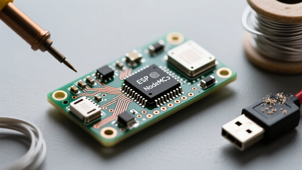
When makers refer to an 'ESP32 NodeMCU', they are typically talking about the ubiquitous NodeMCU-32S clones or ESP32 DevKitC V4 boards. Unlike the original ESP8266 NodeMCU which had a standardized hardware layout, ESP32 development boards vary wildly in their USB-to-UART bridge chips, voltage regulators, and auto-reset circuit implementations. This hardware fragmentation is the root cause of 90% of the compilation, upload, and boot errors encountered in the Arduino IDE. Effective error diagnosis requires looking past the software and understanding the physical limitations of these specific microcontroller boards.
Phase 1: Diagnosing Boot and Strapping Pin Failures
If your ESP32 NodeMCU is stuck in a boot loop or outputs garbage characters at 74880 baud, you are likely witnessing a strapping pin conflict. The ESP32 relies on specific GPIO states during power-on to determine its boot mode. According to the ESP32 Technical Reference Manual, these pins dictate whether the chip boots from SPI flash, enters download mode, or configures the flash voltage.
The GPIO12 Flash Voltage Trap
One of the most insidious hardware errors on ESP32 NodeMCU clones involves GPIO12 (MTDI). This pin is a strapping pin that selects the internal flash voltage. If GPIO12 is pulled HIGH during boot, the ESP32 configures its internal LDO to output 1.8V for the flash memory. However, almost all NodeMCU-32S boards use 3.3V SPI flash chips. If you accidentally wire a sensor or relay to GPIO12 that pulls it high on startup, the board will fail to read the flash, resulting in a continuous boot loop or a 'flash read err, 1000' serial output. Rule of thumb: Never use GPIO12 for outputs or pull-ups on standard ESP32 NodeMCU boards.
GPIO0 and the Download Mode Stubbornness
GPIO0 must be LOW to enter UART bootloader mode. If your board refuses to accept a new sketch and immediately jumps to the existing (possibly corrupted) firmware, GPIO0 is not being pulled low during the reset sequence. This leads directly into upload errors.
Phase 2: Resolving 'Timed Out Waiting for Packet Header'
The most notorious error in the ESP32 ecosystem is the esptool timeout:
A fatal error occurred: Failed to connect to ESP32: Timed out waiting for packet headerThis error means the Arduino IDE successfully compiled your sketch, but the Python-based esptool cannot force the ESP32 into bootloader mode to receive the binary payload.
The Missing Auto-Reset Circuit
Official Espressif DevKits and high-quality NodeMCU boards feature an auto-reset circuit utilizing two NPN transistors (often marked as Q1 and Q2) wired to the DTR and RTS lines of the USB-UART bridge. This circuit automatically pulses the EN (Reset) and GPIO0 (Boot) pins at the exact right microsecond to enter flash mode. Many cheap ESP32 NodeMCU clones omit these transistors to save a few cents. Without them, the software cannot trigger the bootloader.
The Manual Override Fix:
- Connect your board and click 'Upload' in the Arduino IDE.
- Watch the console until you see:
Connecting........_____....._____ - Immediately press and HOLD the 'BOOT' button on the board (pulling GPIO0 low).
- Press and release the 'EN' button (resetting the chip).
- Release the 'BOOT' button. The upload will instantly resume and complete.
CH340 vs. CP2102 Driver Conflicts
If the board doesn't even show up in the IDE ports menu, check the USB-UART chip. NodeMCU-32S boards usually use the CH340C or CP2102. Windows 10 and 11 frequently install generic, incompatible drivers for the CH340. You must manually download the signed CH340 driver from the manufacturer (WCH) and force-install it via Device Manager to restore serial communication.
Phase 3: Runtime Crashes and Power Diagnostics
Once the sketch is uploaded, a new class of errors emerges. The ESP32 is a power-hungry dual-core beast, and clone boards often cut corners on power delivery.
Brownout Detector Triggered
If your serial monitor abruptly halts and prints:
Brownout detector was triggered
abort() was called at PC 0x400d78b9 on core 0
Your ESP32 NodeMCU is experiencing severe voltage sag. The ESP32 can draw up to 500mA during WiFi transmission bursts. The AMS1117-3.3 LDO found on most clone boards has a high dropout voltage and poor transient response. When powered via a long, thin USB cable from a standard 500mA PC USB port, the voltage at the chip drops below 2.4V, triggering the hardware brownout protection and resetting the MCU.
Hardware Fix: Solder a 470µF electrolytic capacitor directly across the 3.3V and GND pins on the board header to act as a transient current reservoir.
Software Fix: Limit the WiFi transmission power to reduce current spikes. Add this to your setup() function:
#include <WiFi.h>
void setup() {
  WiFi.begin(ssid, password);
  // Reduce TX power to 8.5dBm to prevent brownouts on weak LDOs
  WiFi.setTxPower(WIFI_POWER_8_5dBm);
}
Guru Meditation and Watchdog Timeouts
The 'Guru Meditation Error' is the ESP32's equivalent of a Windows Blue Screen. It is generated by the FreeRTOS operating system when a core panics. The most common variant is the Interrupt Watchdog Timeout:
Guru Meditation Error: Core 1 panic'ed (Interrupt wdt timeout on CPU1)As detailed in the Espressif Watchdog Timer Documentation, the Task Watchdog Timer (TWDT) monitors the idle task. If your code contains a tight while() loop without a delay() or yield(), or if you attempt to execute heavy I2C/SPI operations inside an Interrupt Service Routine (ISR), the RTOS is starved of CPU time and triggers the reset. Never use delay() inside an ISR, and always ensure your loop() function yields control back to the FreeRTOS scheduler.
ESP32 NodeMCU Error Diagnosis Matrix
Use this quick-reference table to map your serial monitor output to the root cause and solution.
| Serial Monitor Error / Symptom | Root Cause | Actionable Solution |
|---|---|---|
Timed out waiting for packet header | Missing auto-reset circuit; GPIO0 not pulled LOW during reset. | Use the manual BOOT + EN button sequence during upload. |
Flash read err, 1000 or Boot Loop | GPIO12 pulled HIGH; Flash voltage mismatch (1.8V vs 3.3V). | Remove any pull-up resistors or sensors connected to GPIO12. |
Brownout detector was triggered | Voltage sag during WiFi TX burst; inadequate USB power or LDO. | Add 470µF capacitor on 3.3V rail; lower TX power via software. |
StoreProhibited (Guru Meditation) | Null pointer dereference; accessing uninitialized memory or arrays out of bounds. | Check pointer initialization; use ExceptionDecoder tool to trace the exact line of code. |
Interrupt wdt timeout on CPU1 | FreeRTOS starvation; blocking code in ISR or infinite loop without yield(). | Move heavy processing out of ISRs; add vTaskDelay(1) in tight loops. |
Advanced Debugging: Using the Exception Decoder
When your ESP32 NodeMCU crashes with a memory exception, the serial monitor spits out a backtrace of hex addresses. To translate these into actual line numbers in your Arduino sketch, you need the ESP32 Exception Decoder. You can find this tool and report related core bugs on the Arduino ESP32 Core GitHub Repository. By feeding the hex backtrace into the decoder alongside your compiled .elf file, you can pinpoint exactly which function caused the memory violation, transforming opaque hardware panics into standard software debugging tasks.
Mastering ESP32 NodeMCU error diagnosis requires shifting your mindset from pure software development to embedded systems engineering. By respecting the strapping pins, understanding the limitations of clone board power delivery, and leveraging FreeRTOS-safe coding practices, you can eliminate the vast majority of upload and runtime failures.