
The Hidden Cost of Ad-Hoc ESP32 GPIO Allocation
When prototyping with microcontrollers, it is tempting to wire components to the nearest available pin and define them in firmware later. However, when working with the ESP32 GPIO matrix, this ad-hoc approach is a recipe for catastrophic workflow bottlenecks. Unlike simpler 8-bit microcontrollers, the ESP32 architecture features a highly multiplexed pinout where specific pins dictate boot modes, flash voltages, and peripheral conflicts. A poorly planned pin assignment can result in endless boot loops, silent Wi-Fi failures, and non-linear sensor readings, costing makers and engineering teams hours of debugging.
Optimizing your hardware workflow requires shifting left: planning your ESP32 GPIO allocation before a single jumper wire is connected. By understanding the silicon-level constraints of the ESP32-WROOM-32E, ESP32-S3, and ESP32-C3 families, you can design robust, scalable, and conflict-free hardware architectures. This guide outlines a rigorous, four-phase workflow to master ESP32 pin mapping and eliminate hardware-firmware integration headaches.
Phase 1: Pre-Flight Pin Mapping and Strapping Pin Avoidance
The most common point of failure in ESP32 hardware design involves the "strapping pins." These are specific GPIOs that the chip samples during the reset sequence to determine the boot mode, flash voltage, and log output configuration. If external circuitry (like a sensor pulling a line low, or a relay coil inducing a voltage spike) interferes with these pins during the critical 50-millisecond boot window, the ESP32 will fail to execute your sketch.
According to the Espressif ESP32 Datasheet, mismanaging strapping pins is the leading cause of field-deployment boot failures. Below is the critical strapping pin matrix for the classic ESP32-WROOM module:
| GPIO Pin | Default Internal State | Function if HIGH at Boot | Function if LOW at Boot | Workflow Optimization Rule |
|---|---|---|---|---|
| GPIO 0 | Pulled Up | Normal SPI Flash Boot | Serial Bootloader Mode | Avoid external pull-downs; use 10kΩ pull-up if button is attached. |
| GPIO 2 | Pulled Down | Normal SPI Flash Boot | Download Mode | Never connect to high-impedance sensors; leave floating or pull-down. |
| GPIO 5 | Pulled Up | SDIO Slave Boot | Normal SPI Flash Boot | Ensure external circuits do not pull this low during reset. |
| GPIO 12 (MTDI) | Pulled Down | Flash operates at 1.8V | Flash operates at 3.3V | Critical: Pulling this HIGH will cause a boot loop on 3.3V modules. |
| GPIO 15 (MTDO) | Pulled Up | Normal Boot Log Output | Silences Boot Log (U0TXD) | Safe to use for outputs, but avoid capacitive loads at startup. |
Real-World Failure Mode: A common disaster occurs when engineers connect a relay module with an active-low optocoupler to GPIO 12. During power-on, the optocoupler briefly pulls GPIO 12 HIGH. The ESP32 interprets this as a command to switch the internal SPI flash voltage to 1.8V. Since the WROOM module requires 3.3V, the flash becomes unreadable, resulting in a continuous, unfixable boot loop until the hardware is desoldered.
Phase 2: Navigating the ADC2 and Wi-Fi Collision Zone
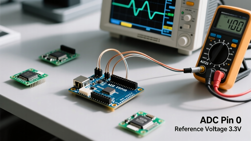
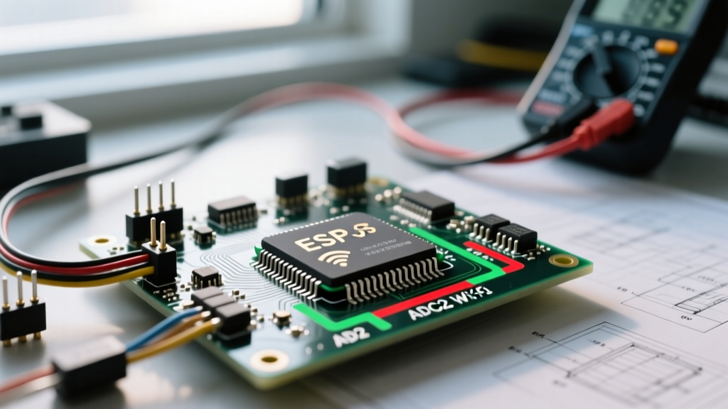
Another major workflow trap involves the Analog-to-Digital Converters. The original ESP32 features two ADC units: ADC1 and ADC2. A hardware limitation dictated by the silicon design means that ADC2 shares internal routing resources with the Wi-Fi MAC layer. If your firmware initializes the Wi-Fi stack (which happens automatically in many Arduino IoT libraries), ADC2 pins become completely inaccessible. Attempting to read from them will yield garbage data or block the thread.
To optimize your analog sensor workflow, adhere to the following allocation strategy:
- Prioritize ADC1 (GPIO 32, 33, 34, 35, 36, 39): These pins operate concurrently with Wi-Fi and Bluetooth. Use them for all critical analog telemetry (e.g., battery voltage monitoring, thermistors, analog joysticks).
- Note Input-Only Restrictions: GPIO 34, 35, 36, and 39 lack internal pull-up/pull-down resistors and are strictly inputs. Your external circuit must provide biasing if required.
- The ADC2 Workaround: If you exhaust ADC1 pins, do not attempt to use ADC2 (GPIO 0, 2, 4, 12-15, 25-27) for real-time analog sensing while Wi-Fi is active. Instead, integrate an external I2C ADC like the ADS1115, which provides 16-bit precision and bypasses the ESP32's internal ADC non-linearity issues entirely.
For newer workflows utilizing the ESP32-S3, Espressif has improved peripheral routing, but the Random Nerd Tutorials ESP32 Pinout Guide still recommends verifying specific module variants, as pins like GPIO 26-32 on the S3-WROOM-1 are often consumed by the internal Octal SPI Flash and PSRAM, rendering them physically unavailable on the breakout headers.
Phase 3: Firmware Abstractions for Scalable Pin Management
Once the physical hardware constraints are mapped, the workflow shifts to firmware architecture. Relying on scattered #define macros or hardcoded integer literals in your setup and loop functions creates technical debt and makes porting code between ESP32 variants nearly impossible.
Professional embedded workflows utilize C++ constexpr within dedicated namespaces or structs. This approach provides compile-time evaluation, strict type checking, and prevents namespace collisions. Furthermore, grouping pins by functional peripherals allows for rapid iteration and automated testing.
// Optimized ESP32 GPIO Mapping Workflow
namespace PinMap {
    // Strapping-safe digital outputs
    constexpr int RELAY_COMPRESSOR = 17;
    constexpr int RELAY_FAN        = 18;
    constexpr int STATUS_LED       = 4; // Safe strapping pin if driven as output post-boot

    // ADC1 Safe Analog Inputs (Wi-Fi Concurrent)
    constexpr int SENSOR_TEMP_AMB  = 32;
    constexpr int SENSOR_HUMIDITY  = 33;
    constexpr int VBAT_SENSE       = 35; // Input only, requires external voltage divider

    // High-Speed UART Mapping
    constexpr int UART1_RX         = 16;
    constexpr int UART1_TX         = 5;
}

void setup() {
    // Example of iterating through an array for batch initialization
    const int output_pins[] = {
        PinMap::RELAY_COMPRESSOR,
        PinMap::RELAY_FAN,
        PinMap::STATUS_LED
    };

    for(int pin : output_pins) {
        pinMode(pin, OUTPUT);
        digitalWrite(pin, LOW); // Ensure safe state on boot
    }
}
By centralizing your ESP32 GPIO definitions, you can easily swap hardware targets. If you migrate from an ESP32-WROOM to an ESP32-C3 (which has only 22 GPIOs and a completely different multiplexing matrix), you only need to update the PinMap namespace rather than hunting through thousands of lines of logic.
Phase 4: Hardware Validation and Debugging Protocols
Even with perfect software mapping, physical layer anomalies can disrupt your workflow. The ESP32's internal pull-up and pull-down resistors are nominally 45kΩ. In electrically noisy environments (e.g., near switching power supplies or brushless DC motors), a 45kΩ pull-up is far too weak to prevent ghost interrupts or false logic triggers.
Implement the following hardware validation protocols before finalizing your PCB or perfboard layout:
- The 10kΩ Rule: For any ESP32 GPIO configured as an interrupt input (such as a rotary encoder or a limit switch), always add an external 10kΩ resistor to 3.3V or GND. This creates a stiff logic state that overrides EMI interference.
- Series Current Limiting: When driving LEDs or optocouplers directly from the ESP32, place a 330Ω to 470Ω series resistor. While the ESP32 GPIO can source up to 40mA per pin, the ESP-IDF GPIO API Documentation strongly advises keeping continuous draw below 20mA to prevent long-term silicon degradation and voltage droop across the chip's internal bonding wires.
- Logic Analyzer Verification: Before deploying to production, use a logic analyzer (like a Saleae or a $15 24MHz clone) to capture the boot sequence. Verify that your strapping pins remain stable for at least 100ms after the EN pin is pulled HIGH, ensuring the internal boot ROM has ample time to latch the correct configuration.
Summary: The Optimized ESP32 Pinout Checklist
Mastering the ESP32 GPIO matrix is less about memorizing datasheets and more about implementing a rigid, defensive design workflow. By front-loading your hardware constraints, respecting the ADC2/Wi-Fi boundary, abstracting your firmware pin mappings, and reinforcing physical logic states with external biasing, you transform the ESP32 from a finicky prototyping toy into a highly reliable industrial controller. Keep your strapping pins isolated, your ADC1 sensors prioritized, and your code modular, and your next embedded project will compile, boot, and run flawlessly on the first power cycle.