
What is a Force Sensitive Resistor (FSR)?
A Force Sensitive Resistor (FSR) is a specialized piezoresistive component whose electrical resistance decreases as the physical pressure applied to its surface increases. Unlike traditional load cells or strain gauges that measure the deformation of a metal element, an FSR relies on a thick-film conductive polymer. For Arduino makers and robotics engineers, the FSR is a staple component for detecting presence, measuring relative grip strength, or triggering events based on physical contact.
However, a common beginner mistake is treating an FSR like a precision laboratory scale. According to Interlink Electronics, the pioneer of FSR technology, these sensors are designed for qualitative or semi-quantitative force measurement. They excel at detecting how hard something is pressing relative to a baseline, but they require careful circuit design and software linearization to output actual force values in Newtons or pounds.
The Physics: Percolation Theory and Piezoresistivity
To understand how to interface an FSR with a microcontroller, you must first understand its internal structure. An FSR consists of two polymer membranes separated by a spacer adhesive. The top membrane is coated with a conductive polymer ink, while the bottom membrane features interdigitated electrodes.
How Pressure Changes Resistance
When no force is applied, the conductive polymer does not touch the electrodes, and the resistance is virtually infinite (typically >10 MΩ). As force is applied, the membranes compress. The conductive polymer makes contact with the electrodes, and the carbon particles within the polymer matrix are forced closer together. This phenomenon is governed by percolation theory: as the distance between conductive particles shrinks, electron tunneling increases, creating more conductive pathways and drastically lowering the overall resistance. Under maximum rated force, the resistance can drop to as low as 200 Ω.
FSR Model Comparison for Arduino Projects (2026 Market)
Choosing the right sensor is critical for project success. Below is a comparison of the most common FSR models available to makers and engineers in 2026.
| Model | Sensing Area | Force Range | Approx. 2026 Price | Best Application |
|---|---|---|---|---|
| Interlink FSR402 | 0.2' diameter | 100g - 10kg | $9.95 | General hobbyist, MIDI triggers |
| Interlink FSR406 | 1.5' diameter | 100g - 10kg | $14.50 | Seat occupancy, large surface mats |
| Tekscan FlexiForce A201 | 0.5' diameter | 0 - 25 lbs | $19.95 | Medical devices, precision robotics |
| Sensitronics FSR Pad | 1.0' x 1.0' | 10g - 10kg | $6.50 | Wearables, budget prototyping |
Note: While the FlexiForce A201 is significantly more expensive, it offers superior linearity and repeatability compared to standard Interlink FSRs, making it the preferred choice when actual Newton force calculations are required (Tekscan FlexiForce Sensors).
Interfacing with Arduino: The Voltage Divider Circuit
Microcontrollers like the Arduino Uno or ESP32 cannot measure resistance directly; their Analog-to-Digital Converters (ADC) measure voltage. Therefore, you must convert the FSR's variable resistance into a variable voltage using a voltage divider circuit.
The Pull-Down Configuration
The standard wiring topology is the pull-down configuration:
- Connect one leg of the FSR to the Arduino's 5V (or 3.3V) pin.
- Connect the other leg of the FSR to an analog input pin (e.g., A0).
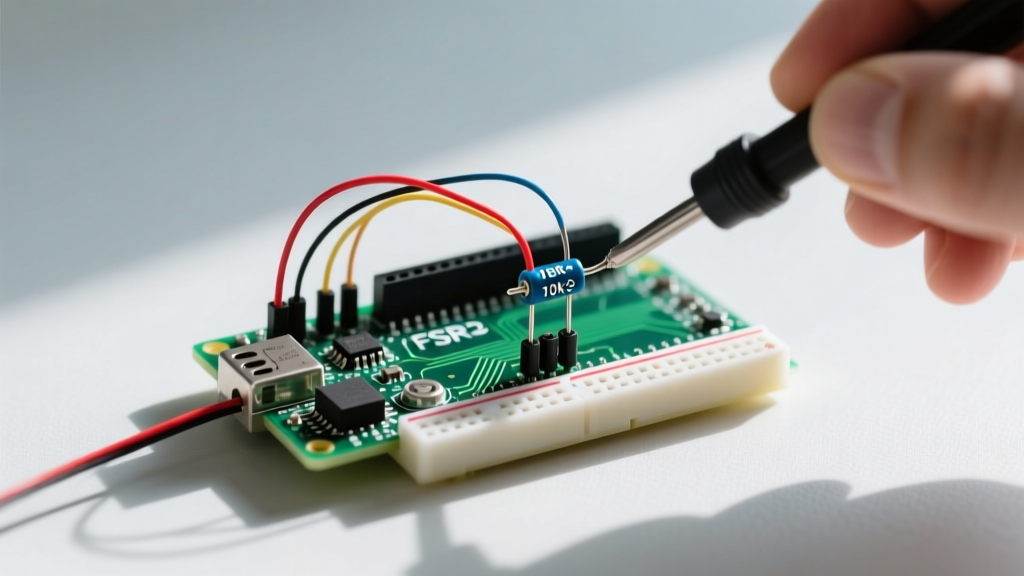
- Connect a fixed pull-down resistor (typically 10 kΩ) between the same analog pin and GND.
The formula for the output voltage ($V_{out}$) read by the Arduino is:
$V_{out} = V_{cc} \times \frac{R_{fixed}}{R_{fsr} + R_{fixed}}$
As you squeeze the FSR, $R_{fsr}$ decreases, which causes the ratio to increase, resulting in a higher voltage at the analog pin. A 10 kΩ fixed resistor is the industry standard because it provides the widest voltage swing across the typical 1 kΩ to 100 kΩ operating range of an FSR402. For a deeper dive into circuit topologies, SparkFun's FSR Hookup Guide provides excellent schematic references.
Arduino Code and the Non-Linear Calibration Problem
If you map the raw ADC values (0-1023 on a 10-bit Arduino Uno) directly to force, you will notice the response is heavily non-linear. The resistance drops exponentially at low forces and flattens out at high forces.
The Conductance Trick for Linearization
To achieve a linear relationship between the sensor output and the applied force, you must calculate the conductance ($G$), which is the reciprocal of resistance ($G = 1/R$). The conductance of an FSR is remarkably linear with respect to applied force.
// FSR Linearization Code Snippet for Arduino Uno
const int fsrPin = A0;
const float Vcc = 5.0;
const float R_fixed = 10000.0; // 10k Ohm pull-down resistor

void setup() {
  Serial.begin(115200);
}

void loop() {
  int adcRaw = analogRead(fsrPin);

  // Convert ADC reading to voltage
  float Vout = (adcRaw / 1023.0) * Vcc;

  // Calculate FSR Resistance
  float R_fsr = R_fixed * ((Vcc / Vout) - 1.0);

  // Calculate Conductance (1/R) for linear force mapping
  float conductance = 0;
  if (R_fsr > 0) {
    conductance = 1000000.0 / R_fsr; // in microMhos
  }

  // Map conductance to Force (requires empirical calibration)
  // Example: Force (N) = conductance * 0.005 (varies by FSR model)
  float forceNewtons = conductance * 0.005;

  Serial.print("Force (N): ");
  Serial.println(forceNewtons);
  delay(100);
}
Real-World Failure Modes and Edge Cases
When moving from a breadboard prototype to a deployed 2026 IoT or robotics project, you must account for the physical limitations of conductive polymers. Ignoring these edge cases will result in erratic data.
1. Hysteresis and Repeatability
FSRs suffer from mechanical hysteresis. If you apply 5 kg of force and release it, the resistance will not immediately return to its exact baseline. Repeatability errors can range from ±5% to ±15%. Mitigation: Implement software deadbands and avoid using FSRs for applications requiring high-precision repetitive weighing.
2. Creep (Drift Under Constant Load)
If you leave a heavy object on an FSR406 for 10 minutes, the analog reading will slowly drift downward by 5% to 10%, even though the physical weight hasn't changed. This is due to the viscoelastic nature of the polymer spacer. Mitigation: Use FSRs only for dynamic measurements or implement a periodic 'tare' routine in your firmware that resets the baseline when the system is known to be unloaded.
3. Shear Force Sensitivity
FSRs are designed to measure perpendicular, compressive force. If a lateral (shear) force is applied, the interdigitated electrodes can scrape against the conductive polymer, causing massive resistance spikes or permanent physical damage to the sensor traces. Mitigation: Always mount the FSR between two rigid, flat plates or embed it in an elastomeric housing that isolates it from lateral friction.
Best Practices for Mechanical Integration
Never press an FSR directly with a bare fingertip or a sharp mechanical point. Point loads create localized stress concentrations that can bottom out the sensor prematurely or puncture the thin polymer layers. Always use a compliant interface material—such as a 2mm thick silicone pad or a piece of high-density EVA foam—between the actuator and the FSR. This distributes the force evenly across the entire active sensing area, ensuring a smooth, predictable resistance curve and drastically extending the operational lifespan of the component.