
The transition to the RISC-V architecture with the ESP32-C3 has introduced incredible cost-efficiency and native USB capabilities to the maker community. However, this architectural shift also brings a unique set of hardware traps, boot failures, and IDE compilation errors that differ significantly from the classic Xtensa-based ESP32.
Whether you are using a bare ESP32-C3-MINI-1 module or a fully populated development board like the ESP32-C3-DevKitM-1, this diagnostic guide isolates the exact failure modes of the C3 variant and provides actionable, board-level fixes.
The ESP32-C3 Diagnostic Matrix
Before diving into deep-dive troubleshooting, map your specific symptom to the root cause using this diagnostic matrix. The C3's single-core RISC-V processor handles interrupts and USB multiplexing differently than its dual-core predecessors.
| Symptom | Root Cause Category | Immediate Action |
|---|---|---|
| "Failed to connect to ESP32: Timed out waiting for packet header" | Boot Mode / Strapping Pins | Force GPIO9 LOW during reset, or check USB CDC settings. |
| Continuous reboots with "Brownout detector was triggered" | Power Delivery / LDO Sag | Measure 3.3V rail under Wi-Fi TX load; upgrade LDO or add bulk capacitance. |
| USB device not recognized in Windows/Linux (No COM port) | Native USB-JTAG Driver | Install Zadig/WinUSB drivers or verify physical GPIO18/19 routing. |
| Arduino IDE: "fatal error: esp_rom_sys.h: No such file or directory" | RISC-V Toolchain Mismatch | Update ESP32 Board Manager to v2.0.14+ and clear compilation cache. |
Resolving Native USB and Serial Upload Failures
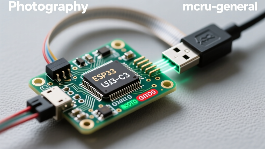
Unlike the original ESP32, which relied entirely on an external UART-to-USB bridge (like the CP2102 or CH340), the ESP32-C3 features an internal USB Serial/JTAG controller. This allows direct programming via pins GPIO18 (D-) and GPIO19 (D+). However, this dual-path routing is the source of 80% of upload errors.
Scenario A: Using the Native USB Port
If your dev board exposes the native USB directly to a Type-C connector, the Arduino IDE must be configured to use the internal CDC (Communications Device Class). If you forget this, the bootloader will wait for a UART handshake that never arrives.
- Arduino IDE Fix: Go to Tools > USB CDC On Boot and set it to Enabled.
- Driver Fix: On Windows 10/11, the C3 should enumerate automatically. If it shows as an "Unknown Device" or "JTAG" device, use Zadig to replace the driver with WinUSB.
Scenario B: Using an External UART Bridge
Many third-party "C3" boards still route an external CH340 to the standard UART0 pins (GPIO20 RX, GPIO21 TX) to maintain compatibility with legacy code. If you are using the UART port but the IDE is trying to use the internal USB-JTAG interface, uploads will fail.
Pro Tip: If your board has two USB ports (one labeled "USB", one labeled "UART"), always use the UART port for initial flashing if the native USB bootloader is corrupted or locked out by secure boot eFuses.
Strapping Pin Conflicts: GPIO8 and GPIO9
The ESP32-C3 relies on strapping pins to determine the boot mode and debug logging behavior during the ROM bootloader phase. Designing custom PCBs or wiring sensors to these pins without pull-up/pull-down resistors will result in erratic boot loops.
The Critical Strapping Pins
- GPIO9 (Boot Mode): Must be LOW to enter SPI Flash Download mode. If pulled HIGH (or left floating and affected by noise), the chip will attempt to boot from SPI flash. If the flash is empty or corrupted, it halts silently.
- GPIO8 (Debug Logging): Controls ROM message printing. If pulled LOW, the ROM bootloader prints debug logs to UART0. If HIGH, it suppresses them.
Hardware Fix: If your sketch hangs on boot and you are using GPIO9 for an external interrupt or sensor, you must add a 10kΩ pull-down resistor to GND to ensure it defaults to the correct state during the 50ms reset window. For detailed schematic guidelines, always refer to the Espressif Hardware Design Guidelines.
Power Delivery and the Brownout Detector (BOD)
The ESP32-C3 is highly efficient in deep sleep (drawing ~5µA), but its Wi-Fi transmission bursts are aggressive. During a Wi-Fi TX burst, the C3 can draw upwards of 350mA for fractions of a millisecond.
Why the BOD Triggers
Many budget-friendly ESP32-C3 clone boards utilize cheap, low-spec 3.3V LDOs (Low Dropout Regulators) rated for only 150mA or 300mA continuous current. When the Wi-Fi radio initializes, the instantaneous current draw causes the LDO output voltage to sag below the ESP32-C3's brownout threshold (typically ~2.3V). The internal BOD immediately triggers a hardware reset to protect the flash memory from under-voltage corruption.
Fixing the Brownout Loop
- Measure the Sag: Use an oscilloscope (a standard multimeter is too slow to catch a 5ms voltage droop) on the 3.3V pin while triggering a Wi-Fi scan.
- Add Bulk Capacitance: Solder a 100µF to 470µF low-ESR tantalum or ceramic capacitor directly across the 3.3V and GND pins on your breadboard or custom PCB.
- Bypass via Software (Not Recommended): You can disable the BOD in the Arduino IDE via Tools > Core Debug Level or by writing directly to the RTC_CNTL register in your setup function, but this risks flash corruption during power drops.
RISC-V Toolchain and IDE Compilation Errors
Because the ESP32-C3 uses a 32-bit RISC-V core instead of the Xtensa LX6/LX7 cores found in the ESP32 and ESP32-S3, it requires an entirely different GCC toolchain. If you are migrating code from an older ESP32 project, you will likely hit compiler errors.
Common Compilation Failures
A frequent error when updating the Arduino ESP32 Core is the fatal error: esp_rom_sys.h: No such file or directory. This occurs when the IDE attempts to compile legacy ESP-IDF v3.3 macros against the newer ESP-IDF v4.4/v5.1 architecture that the C3 demands.
- The Fix: Open the Arduino IDE Boards Manager, search for "esp32", and ensure you are on version 2.0.14 or newer. Delete the
~/.arduino15/packages/esp32cache folder on your OS to force a clean download of the RISC-V toolchain binaries.
Navigating the 400KB SRAM Limitation
Unlike the ESP32-WROVER modules that boast 4MB of PSRAM, the ESP32-C3 is strictly limited to its internal 400KB SRAM. Of this, roughly 120KB is reserved for the Wi-Fi/BLE stack and OS interrupts. This leaves makers with approximately 280KB of usable heap memory.
If you are porting a project that uses large JSON parsing libraries (like ArduinoJson) or extensive OLED display buffers, you will quickly encounter esp_err_t allocation failures or silent reboots.
- Data Structure Optimization: Always declare large lookup tables, HTML strings for web servers, and SSL certificates using the
const char*type. This forces the RISC-V linker to place the data in the read-only Flash partition (IROM) rather than consuming precious DRAM at boot. - Heap Monitoring: Implement
ESP.getFreeHeap()andESP.getMinFreeHeap()in your main loop to track memory fragmentation over time. If the minimum free heap drops below 20KB during Wi-Fi provisioning, the C3 will fail to allocate the necessary crypto buffers for the TLS handshake.
Final Verification Steps
Before assuming your ESP32-C3 module is bricked, perform the "Manual Bootloader Entry" sequence. Hold the BOOT button (pulling GPIO9 LOW), press and release the RESET button, and then release the BOOT button. If the serial monitor suddenly outputs the MAC address and flash parameters, your chip is healthy, and your issue is strictly related to auto-reset circuitry or strapping pin conflicts in your hardware design.