
The Thumb-Sized Revolution: Why Makers Choose XIAO
The Seeed Studio XIAO series has fundamentally shifted how the maker community approaches compact IoT and wearable projects. Measuring a mere 21 x 17.5mm, these boards pack the full power of Espressif's silicon into a footprint smaller than a postage stamp. However, as thousands of makers on forums and GitHub repositories have documented, shrinking the board size introduces unique hardware quirks. This community resource guide synthesizes real-world troubleshooting, hardware modifications, and best practices for the ESP32 XIAO lineup, specifically focusing on the C3, S3, and C6 variants.
Community Consensus: Which Chip Variant Do You Actually Need?
Choosing between the XIAO ESP32C3, ESP32S3, and ESP32C6 is the first hurdle. Based on community project post-mortems, here is how makers are segmenting their use cases:
| Feature | XIAO ESP32C3 | XIAO ESP32S3 | XIAO ESP32C6 |
|---|---|---|---|
| Architecture | RISC-V Single-Core | Xtensa Dual-Core | RISC-V Single-Core |
| Wireless | Wi-Fi 4, BLE 5.0 | Wi-Fi 4, BLE 5.0 | Wi-Fi 6, BLE 5.3, 802.15.4 |
| USB Native | No (Uses Bridge) | Yes (USB OTG) | No (Uses Bridge) |
| Best For | Ultra-low cost, basic sensors | Camera, Audio, AI Edge | Smart Home (Thread/Zigbee) |
| Approx. Price | $4.99 | $8.99 | $6.99 |
According to discussions on the Seeed Studio Wiki, the S3 is the undisputed king for projects requiring native USB HID capabilities or local machine learning inference, while the C6 has become the community default for Matter and Thread-based smart home nodes.
Navigating the Pinout Quirks and Hardware Gotchas
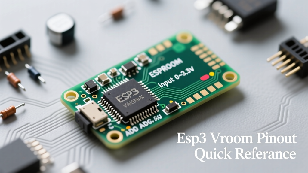
When you shrink a development board, you inevitably run out of pins, meaning every GPIO must do double duty. This leads to the infamous 'strapping pin' conflicts that plague beginners.
The Strapping Pin Trap
Espressif chips use specific GPIO pins to determine boot modes. If you wire a sensor or a pull-down resistor to these pins, your ESP32 XIAO will refuse to boot your sketch.
- XIAO ESP32C3: GPIO9 is the primary boot strapping pin. Community members frequently report boot loops when connecting push-buttons to GPIO9 without a proper pull-up resistor. Keep GPIO9 floating or pulled HIGH during boot.
- XIAO ESP32S3: GPIO0, GPIO3, GPIO45, and GPIO46 are strapping pins. The most common community mistake is using GPIO0 for an I2C interrupt line. If the line is pulled low at startup, the S3 enters serial download mode and will not execute your code.
The USB CDC Serial Trap (S3 Specific)
Because the XIAO ESP32S3 features native USB, it does not use a traditional UART-to-USB bridge chip. A massive time-waster documented across maker forums is the 'missing Serial output' bug. If you open the Arduino IDE and fail to set USB CDC On Boot to Enabled in the Tools menu, your code will compile and upload perfectly, but Serial.println() will output to nowhere. Always verify this setting before debugging complex code.
The U.FL vs. Onboard Antenna Dilemma
Range is critical for IoT, and the XIAO series offers both an onboard PCB antenna and a U.FL connector for external antennas. However, the switching mechanism differs wildly between models, leading to burned-out RF stages or dead signals.
Community Warning: Never power the XIAO ESP32S3 with an external antenna attached unless you have explicitly triggered the RF switch in your code. Sending full TX power into an unswitched U.FL connector can damage the matching network.
On the XIAO ESP32S3, an RF switch chip is used. You must set GPIO14 to HIGH in your setup routine to route the signal to the U.FL connector. Conversely, the XIAO ESP32C3 lacks an active RF switch. Instead, it uses a 0-ohm resistor pad on the PCB. To use an external antenna on the C3, you must physically desolder the tiny 0-ohm resistor from the onboard antenna pad and move it to the U.FL pad. For a comprehensive hardware breakdown, refer to the XIAO ESP32C3 official documentation.
Deep Sleep Current: The Great Battery Drain Mystery
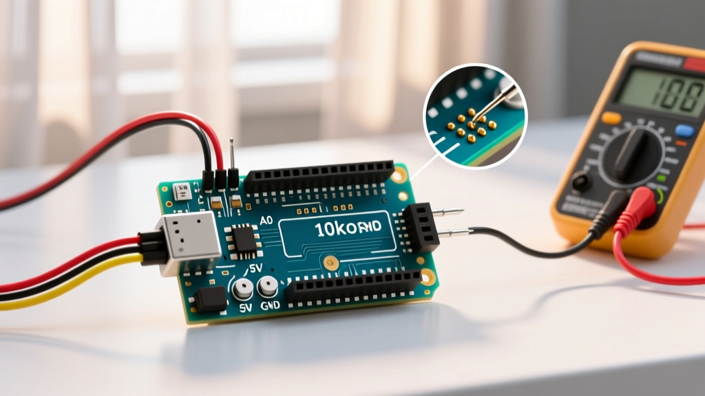
Espressif advertises deep sleep currents in the single-digit microamp range (typically 5µA to 10µA). However, when community members measure the XIAO boards powered via the JST battery connector, they frequently observe 1.5mA to 3mA of quiescent draw. This drains a 500mAh LiPo in a matter of days, not months.
Identifying the Parasitic Draw
The culprit is not the ESP32 chip itself, but the supporting power management circuitry on the XIAO breakout board. Specifically, the onboard LiPo charge IC (often a variant of the TP4054 or SGM4056) and the 3.3V LDO regulator possess quiescent current leaks that remain active even when the ESP32 is in deep sleep.
Measured Quiescent Currents and Hardware Mods
Through collaborative testing, the community has mapped out the exact current draws based on power delivery methods:
- Stock Board (Battery via JST): ~1.5mA (Charge IC quiescent draw).
- Powering via 5V Pin: ~150µA (Bypasses battery charge IC, but LDO still draws current).
- The 'Deep Sleep Mod' (Desoldered Charge IC + 3.3V Direct): ~12µA (C3) or ~18µA (S3).
To achieve true ultra-low power, advanced makers physically desolder the battery charging IC using a hot air rework station and power the board directly via the 3.3V pin using an external, highly efficient switching buck converter. While this sacrifices the convenience of USB battery charging, it is the only way to achieve the Espressif documented deep sleep metrics for off-grid solar or coin-cell applications.
Power Delivery and Battery Charging Nuances
If you choose to keep the charging circuit intact, you must understand the limits of the XIAO's power delivery. The onboard charge IC is typically rated for a maximum of 400mA to 500mA charging current. If you pair the board with a massive 5000mAh LiPo battery, expect charging times to exceed 12 hours. Furthermore, the charge IC lacks advanced battery temperature monitoring (NTC thermistor support). The community strongly advises against leaving XIAO boards unattended while charging high-C-rate LiPo pouch cells in enclosed 3D-printed enclosures.
Essential Community Resources and Next Steps
Mastering the ESP32 XIAO requires looking beyond the basic blink sketches. By understanding the strapping pin limitations, properly configuring the RF antenna switches, and addressing the parasitic power draws of the onboard LDOs, you can transform this tiny board into a robust, production-ready IoT node. Before finalizing your PCB carrier board design, always spin up a prototype on a breadboard and validate your deep sleep currents with a dedicated current multimeter like the Nordic PPK2 or a standard benchtop DMM in microamp mode.