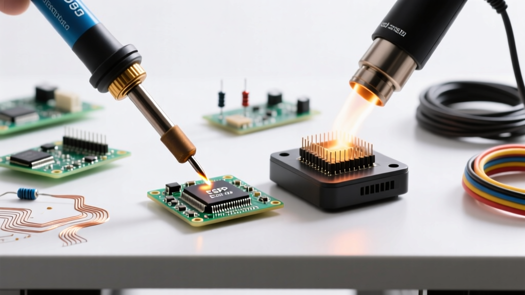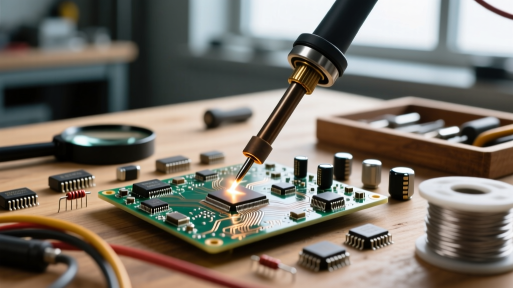

Dialing in the exact solder temperature for electronics is rarely a simple matter of matching your iron's dial to the alloy's melting point. Whether you are hand-soldering a delicate 0402 surface-mount resistor or dragging a heavy 10AWG wire to a massive ground plane, the thermal dynamics of your workstation dictate the reliability of your final assembly. In this comprehensive FAQ and troubleshooting guide, we dissect the metallurgy of solder joints, provide exact temperature matrices, and solve the most common thermal failures encountered in PCB assembly.
The Core Dilemma: Melting Point vs. Iron Setting
A frequent mistake among beginners is setting the soldering station to the exact melting point of the solder alloy. For example, standard 63/37 tin-lead solder melts at 183°C (361°F). If you set your iron to 185°C, the joint will likely fail to form. Why? Because the PCB pad, the component lead, and the flux all act as heat sinks, rapidly pulling thermal energy away from the tip. By the time the heat transfers through the tip's chrome plating and into the copper pad, the actual temperature at the interface drops well below the melting threshold.
To achieve a proper metallurgical bond, your iron must be set significantly higher than the alloy's liquidus temperature to provide a thermal 'delta' that overcomes the joint's thermal mass. However, setting the temperature too high introduces a new set of catastrophic failures, including tip oxidation, flux carbonization, and substrate delamination.
Quick-Reference Temperature Matrix for Common Alloys
The table below outlines the baseline parameters for the most common electronics solder alloys. These recommended iron temperatures assume a standard 1.5mm to 2.4mm chisel tip and a moderate thermal mass joint.
| Alloy Designation | Composition | Melting Point (Liquidus) | Recommended Iron Temp | Max Dwell Time |
|---|---|---|---|---|
| Sn63/Pb37 | 63% Sn, 37% Pb | 183°C (361°F) | 300°C - 330°C | 2 - 3 seconds |
| SAC305 | 96.5% Sn, 3.0% Ag, 0.5% Cu | 217°C - 220°C | 340°C - 360°C | 2 - 4 seconds |
| Sn99.3/Cu0.7 | 99.3% Sn, 0.7% Cu | 227°C (441°F) | 350°C - 380°C | 3 - 4 seconds |
| Sn42/Bi58 | 42% Sn, 58% Bismuth | 138°C (280°F) | 240°C - 260°C | 1 - 2 seconds |
The Metallurgy of Heat: Intermetallic Layers Explained
Understanding the why behind these temperature settings requires a brief look at metallurgy. A reliable solder joint is not just melted metal sitting on top of copper; it is a chemical bond. When molten tin contacts copper, they react to form an Intermetallic Compound (IMC) layer, primarily Cu6Sn5 and Cu3Sn. According to Adafruit's Guide to Excellent Soldering, this IMC layer is the actual mechanical and electrical bridge of the joint.
If your solder temperature for electronics is too low, the IMC layer fails to form, resulting in a weak, cold joint. If the temperature is excessively high, or if the iron dwells on the pad for too long, the IMC layer grows too thick. A thick IMC layer is highly brittle and will easily crack under mechanical stress or thermal cycling, leading to latent field failures that are notoriously difficult to diagnose.
Troubleshooting Thermal Failures in PCB Assembly
When your solder joints fail visual inspection or continuity testing, the root cause is almost always thermal mismanagement. Here is how to troubleshoot the most common symptoms.
Symptom: Dull, Grainy, or 'Cold' Joints
A proper tin-lead joint should look shiny and smooth, while lead-free joints will naturally appear slightly duller but should still exhibit a smooth, concave fillet. If the joint looks grainy, lumpy, or resembles a cluster of grapes, you have a cold joint.
- Cause 1: Insufficient Iron Temperature. The iron failed to bring the entire thermal mass of the pad and lead above the liquidus point simultaneously. The solder solidified while the components were still expanding or moving.
- Cause 2: Premature Flux Depletion. If the heat transfer is too slow, the flux boils off and carbonizes before the solder can wet the copper, leaving an oxide layer that prevents bonding.
- Fix: Increase your station temperature by 20°C, switch to a wider chisel tip to maximize surface area contact, and apply fresh external flux.
Symptom: Lifted Pads and Delaminated FR4
If the copper pad peels away from the fiberglass substrate (FR4) when you remove the iron, you have exceeded the thermal limits of the PCB material. Standard FR4 has a Glass Transition Temperature (Tg) between 130°C and 170°C. While it can withstand brief excursions to 260°C during wave soldering, prolonged localized heat from a 400°C iron will vaporize the moisture inside the resin and destroy the epoxy bond holding the copper foil.
- Cause: Iron temperature set too high (often above 380°C for standard boards) combined with a dwell time exceeding 5 seconds.
- Fix: Lower the temperature, use a PCB preheater to raise the ambient baseline of the board to 100°C, and practice the '3-second rule'—if the joint doesn't flow in 3 seconds, remove the iron, let the pad cool, add flux, and try again.
Symptom: Flux Charring and Poor Wetting
Rosin-based fluxes (RMA, RA) are designed to activate and clean oxides between 150°C and 200°C. If you see black, crusty residue burning onto your tip or the PCB silkscreen, your iron is far too hot. This carbonized flux acts as an insulator, preventing the solder from wetting the pad.
- Fix: Drop your iron temperature to the lower end of the recommended matrix. Clean the tip immediately using damp brass wool, and never leave a hot iron sitting in its holder without a protective blob of solder on the tip.
Managing Thermal Mass Without Cranking the Dial
A common scenario in electronics repair is soldering a thick wire to a massive ground plane. The ground plane acts as an enormous heat sink, instantly sucking the thermal energy out of your soldering tip. Many technicians react by cranking their station to 450°C. This is a critical error. It will instantly oxidize your tip (rendering it useless) and scorch the board.
The correct approach to managing high thermal mass is to increase the thermal transfer rate, not necessarily the peak temperature. As detailed in SparkFun's Soldering Tutorial, you can achieve this by switching to a massive bevel or wide chisel tip. A larger tip holds more thermal energy in its core and provides a wider surface area for conduction. Additionally, applying polyimide (Kapton) tape around the work area can protect nearby sensitive plastic connectors from radiant heat while you focus the thermal output on the heavy joint.
Frequently Asked Questions (FAQ)
Can I just leave my iron at 400°C for everything to save time?
No. Operating a standard iron at 400°C (752°F) continuously will cause rapid oxidation of the iron plating on the tip. Once the tip turns black and crusty, solder will no longer wet to it, forcing you to scrap the tip. Furthermore, high heat accelerates the dissolution of the tip's copper core, leading to pitting and cratering. Only use high temperatures (380°C+) for brief periods on heavy thermal mass joints, and immediately drop back to 320°C for standard work.
Why does my lead-free solder refuse to flow even at 350°C?
Lead-free alloys like SAC305 have higher surface tension and poorer wetting characteristics than tin-lead. If it is balling up and refusing to flow, your flux is likely failing. Lead-free solders require highly active, no-clean or water-soluble fluxes designed specifically for higher temperatures. Apply a generous amount of high-quality tack flux to the pad before introducing the iron and solder wire.
How do I know if my soldering station's temperature readout is lying?
Digital readouts on budget stations measure the temperature of the heating element inside the ceramic core, not the actual tip. If the tip is loose, oxidized, or damaged, there will be a massive thermal drop between the sensor and the tip. To verify, use a tip thermometer (a specialized thermocouple device) or test the iron's ability to melt a known alloy within the standard 2-3 second dwell time.
Expert Troubleshooting Tip: If you are consistently struggling with the ideal solder temperature for electronics on a specific board, stop guessing. Invest in an infrared thermal camera or a PCB preheater. Raising the ambient temperature of the entire PCB to 80°C - 100°C means your hand iron only needs to bridge a 150°C delta instead of a 250°C delta, resulting in pristine joints and zero pad damage.