
Beyond the Breadboard: Analyzing the Community's Best Robot Arm Builds
If you have spent any time on Hackaday, r/robotics, or Instructables, you know the familiar arc of the DIY robotics journey. You search for how to make a robot arm, buy a cheap acrylic kit with blue TowerPro servos, wire it to an Arduino Uno, and watch it jitter violently before your microcontroller resets. Building a functional, multi-axis robotic manipulator is a rite of passage, but the gap between a "working prototype" and a "reliable machine" is vast.
Instead of another generic step-by-step assembly guide, we have analyzed hundreds of community builds from 2023 through 2026 to distill what actually works. This showcase breaks down the dominant archetypes of DIY robot arms, the critical power supply pitfalls that ruin 90% of first-time builds, and the shift toward smart bus servos that is redefining home automation and desktop manufacturing.
The Three Dominant Community Archetypes
When figuring out how to design your manipulator, the community generally gravitates toward one of three distinct build philosophies. Your choice dictates your budget, payload capacity, and required microcontroller.
| Archetype | Primary Materials | Actuators | Avg. Cost | Best Use Case |
|---|---|---|---|---|
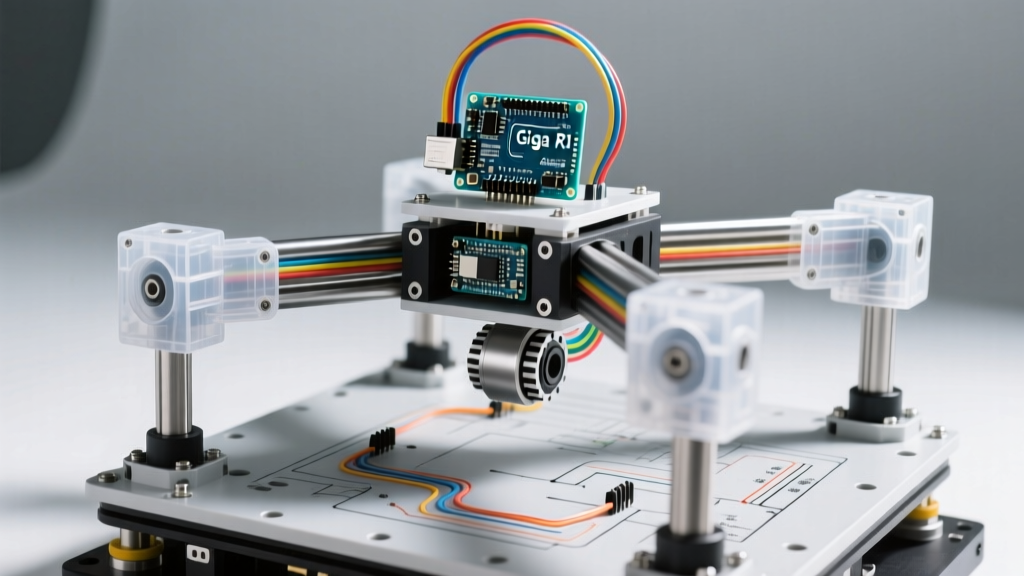
| The E-Waste Scavenger | Upcycled DVD drives, aluminum brackets | 28BYJ-48 Steppers + ULN2003 | $25 - $45 | Micro-drawing, learning kinematics, light pick-and-place. |
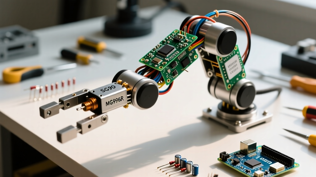
| The 3D Printed Workhorse | PETG/ABS printed joints, M4 threaded rods | MG996R or DS3218 PWM Servos | $120 - $200 | Desktop sorting, camera gimbals, educational demonstrations. |
| The Serial Bus Precision | CNC machined aluminum or carbon fiber | STS3215 or LX-16A Bus Servos | $350 - $600+ | Light manufacturing, chess-playing AI, closed-loop control. |
The #1 Failure Mode: Power Supply Bottlenecks
The most common reason community members abandon their robot arm projects is the "brown-out epidemic." A standard Arduino Uno powered via USB can supply roughly 500mA. A single MG996R servo under stall load can draw up to 2.5A. If your 4-DOF (Degree of Freedom) arm attempts to lift a payload and three servos stall simultaneously, you are suddenly demanding 7.5A from a system designed for 0.5A.
The Wrong Way: Linear Regulators and Cheap Buck Converters
Many beginners attempt to use LM2596 buck converters to step down a 12V laptop brick to 5V. While these are rated for "3A continuous," they lack the transient response required for the inductive spikes of servo motors. The voltage sags, the Arduino's ATmega328P resets, and the arm goes limp, potentially damaging your 3D printed gears as gravity takes over.
The Community Standard: Industrial SMPS and Star Grounding
The gold standard for reliable DIY arms is a dedicated Switched-Mode Power Supply (SMPS). Builders consistently recommend the Mean Well LRS-100-5 (5V, 20A, ~$18). This provides massive headroom for transient current draws. Furthermore, veteran builders enforce a "star ground" topology: the ground from the power supply, the ground from the microcontroller, and the grounds from the servos all meet at a single, thick terminal block. This prevents ground loops and ensures the PWM or serial signals remain clean.
Pro-Tip from the Bench: Always place a 1000µF electrolytic capacitor and a 0.1µF ceramic decoupling capacitor across the VCC and GND pins of every single servo. This local energy reservoir absorbs high-frequency voltage spikes generated by the internal DC motors, drastically reducing signal jitter and extending the life of your microcontroller.
The Servo Revolution: PWM vs. Serial Bus
For over a decade, the Pololu RC Servos catalog and similar hobby shops were dominated by standard PWM (Pulse Width Modulation) servos. You send a 1-2ms pulse every 20ms, and the servo moves. But PWM is open-loop; the microcontroller has no idea if the arm actually reached the target position or if it is stuck against an obstacle.
Enter the Smart Bus Servo
The most significant shift in recent community showcases is the adoption of half-duplex serial bus servos like the Waveshare STS3215 or the LewanSoul LX-16A. These actuators communicate via a TTL serial protocol (often requiring a custom UART shield). The information gain here is massive:
- True Positional Feedback: You can query the servo for its exact current angle, enabling compliance mode (the arm yields when a human pushes it).
- Temperature & Voltage Telemetry: Prevent burnout by programming the MCU to shut down the arm if internal servo temps exceed 85°C.
- PID Tuning: Adjust the Proportional-Integral-Derivative values on the fly to eliminate overshoot when moving heavy payloads.
Microcontroller Selection: Why the Arduino Uno Falls Short
When learning how to make a robot arm, most tutorials default to the Arduino Servo Library Documentation. While excellent for basic sweeping, the Uno lacks a Floating Point Unit (FPU). Calculating Inverse Kinematics (IK)—the trigonometric math required to figure out what angles the shoulder and elbow must be at to place the gripper at a specific X, Y, Z coordinate—requires heavy `atan2`, `sqrt`, and `cos` calculations.
On an ATmega328P, these floating-point operations are done in software, causing noticeable lag and stuttering in the arm's trajectory. The community has overwhelmingly migrated to the ESP32 or the Teensy 4.1 for kinematic arms. The ESP32 offers dual-core processing, hardware FPU, and built-in Wi-Fi for ROS (Robot Operating System) bridge integration, all for under $8.
Signal Isolation: The PCA9685 Mandate
If you are sticking to PWM servos for budget reasons, never drive them directly from the microcontroller's GPIO pins. The electrical noise from the servo motors will corrupt your logic levels. The Adafruit PCA9685 PWM Servo Shield Guide remains the definitive resource for implementing this I2C-based PWM driver. It isolates the high-current motor timing from your sensitive MCU, handles the 12-bit resolution smoothly, and allows you to daisy-chain multiple boards for 6-DOF or 7-DOF humanoid arms.
Assembly Realities: Dealing with Backlash and Flex
No matter how perfect your CAD model is, physical DIY robot arms suffer from backlash (the slight gap between gear teeth) and link flex. Community builders mitigate this through a few clever mechanical tricks:
- Pre-tensioning: Using wave washers on the shoulder and elbow joints to apply constant axial load, eliminating vertical slop.
- Cross-Roller Bearings: Replacing cheap radial ball bearings with cross-roller thrust bearings at the base rotation joint to handle the massive cantilevered moment arm.
- Software Deadzones: Implementing a software deadband in the IK solver so the microcontroller doesn't send micro-corrections that cause the arm to "hunt" or vibrate when holding still.
Final Thoughts: Start Small, Iterate Fast
Building a robotic manipulator is an exercise in managing trade-offs between torque, speed, precision, and budget. If this is your first time tackling how to make a robot arm, start with a 3-DOF planar arm using an ESP32 and an I2C PWM driver. Master the power delivery, write a basic forward-kinematics visualizer in Python, and only then scale up to 6-DOF spatial arms with serial bus actuators. The community's greatest lesson is that a well-powered, mathematically sound 3-DOF arm will always outperform a sagging, brown-out-prone 6-DOF monstrosity.