
Diagnosing Raspberry Pi GPIO Pinout Wiring Errors
When a maker transitions from the forgiving 5V logic of an Arduino Uno to the Raspberry Pi ecosystem, the learning curve is often paved with fried silicon. The Raspberry Pi GPIO pinout is a marvel of compact I/O, offering multiple multiplexed functions per pin, but it lacks the robust overvoltage tolerance of traditional ATmega microcontrollers. Error diagnosis on the Pi requires a dual approach: verifying physical hardware integrity and untangling software-level pin mapping conflicts. Whether you are dealing with a completely unresponsive I2C bus, a boot-looping UART configuration, or a dead GPIO bank, this diagnostic guide will help you isolate the root cause of your Pi GPIO pinout failures.
The 3.3V vs 5V Catastrophe: Diagnosing Fried GPIO Banks
The most common fatal error when interfacing external components with the Raspberry Pi is ignoring the 3.3V logic level limit. Unlike the Arduino's ATmega328P, which natively tolerates 5V on its I/O pins, the Broadcom BCM283X (and the RP1 chip on the Pi 5) operates strictly at 3.3V. Internal ESD protection diodes clamp any voltage above ~3.6V to the 3.3V rail. If you connect a 5V sensor output directly to a Pi GPIO pin without a level shifter (like the BSS138 or 74LVC245), the diode conducts excessive current, overheats, and permanently shorts the pin to the VCC rail.
The Multimeter Resistance Test
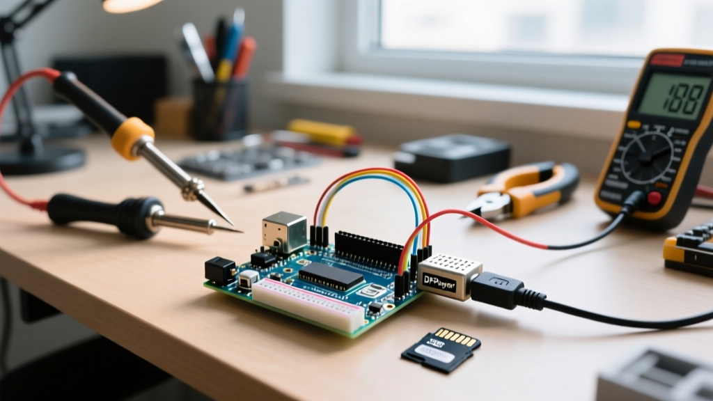
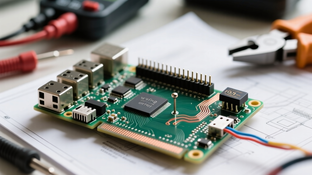
To diagnose a suspected fried pin, you must power down the Pi completely and disconnect all peripherals. Set your digital multimeter (DMM) to resistance mode (Ohms). Place the black probe on a known good ground pin (e.g., Physical Pin 6) and the red probe on the suspect GPIO pin.
- Healthy Pin: Reads >10kΩ (often in the MΩ range) or shows an open circuit.
- Compromised/Shorted Pin: Reads between 10Ω and 50Ω. This indicates the internal clamping diode has melted into a dead short.
- Open/Blown Trace: If the pin was subjected to severe overcurrent, the internal silicon trace may have vaporized, resulting in an infinite resistance reading (OL) even when toggled high via software.
If you confirm a pin is dead, your only hardware-level workaround is to blacklist that specific BCM pin in your code and route your wiring to an adjacent spare pin, referencing a comprehensive map like Pinout.xyz to ensure the alternate pin doesn't have a conflicting hardware overlay.
Software vs Hardware Mismatches: BOARD vs BCM Numbering
A massive source of 'silent' errors—where code compiles and runs but nothing happens—stems from confusing Physical Pin numbering with Broadcom (BCM) SOC channel numbering. The physical pinout consists of 40 pins, but the BCM numbering scheme maps only to the specific GPIO identifiers inside the silicon die.
For example, if you physically wire an LED to Physical Pin 31, but your Python script using the RPi.GPIO library is set to GPIO.setmode(GPIO.BCM) and targets pin 31, you are actually addressing BCM 31 (which corresponds to Physical Pin 36). Your LED on Physical Pin 31 will never light up.
Commonly Miswired Pin Matrix
| Physical Pin | BCM GPIO | Primary Function | Common Diagnostic Error |
|---|---|---|---|
| 3 | 2 | SDA1 (I2C) | Confusing BCM 2 with Physical Pin 2 (5V Power) |
| 5 | 3 | SCL1 (I2C) | Accidentally wiring to BCM 5 (Physical 29) |
| 8 | 14 | TXD (UART) | Crossing TX/RX without checking BCM mapping |
| 29 | 5 | GPIO 5 | Assuming Physical 29 is BCM 29 (BCM 29 is Pin 40) |
| 31 | 6 | GPIO 6 | Assuming Physical 31 is BCM 31 (BCM 31 is Pin 36) |
Fix: Always explicitly declare your numbering scheme at the top of your script. If you are wiring based on the physical silk-screen on a third-party GPIO breakout board, use GPIO.setmode(GPIO.BOARD). If you are wiring based on schematic BCM labels, use GPIO.setmode(GPIO.BCM).
Protocol-Specific Failures: I2C, SPI, and UART Lockups
When the pinout is physically correct and the software mapping is verified, protocol-level electrical conflicts are the next diagnostic target.
I2C Bus Lockups and Pull-Up Conflicts
The Raspberry Pi's primary I2C bus (Physical Pins 3 and 5, BCM 2 and 3) features onboard 1.8kΩ pull-up resistors tied to the 3.3V rail. A frequent error occurs when makers connect a 5V Arduino or a generic I2C breakout board that has its own 4.7kΩ pull-ups tied to 5V. This creates a voltage divider that pushes the Pi's SDA/SCL lines above 3.3V, or worse, backfeeds 5V directly into the Pi's I2C controller when the Pi pulls the line low.
Diagnostic Symptom: Running i2cdetect -y 1 yields a blank grid, or the entire Pi freezes, requiring a hard reboot.
Resolution: Remove external pull-up resistors from any sensor module connected to Pins 3 and 5. If you must interface 5V I2C devices, use a dedicated bidirectional logic level converter with isolated pull-ups on both the high and low sides.
UART Boot Console Interference
Physical Pins 8 (TX) and 10 (RX) default to the Linux serial console. If you wire a microcontroller (like an ESP32) to these pins to send sensor data, the Pi's boot process will halt or behave erratically because the kernel is trying to negotiate a login shell with your sensor. Furthermore, sending 5V logic from the ESP32 into the Pi's RX pin (Physical 10) will destroy the UART receiver block.
To diagnose and fix UART conflicts, you must edit the boot configuration. On modern Raspberry Pi OS (Bookworm and later), this is handled via Raspberry Pi Configuration Documentation standards in /boot/firmware/config.txt. Add enable_uart=1 and ensure the serial console is disabled in raspi-config under Interface Options. If using the primary UART for non-console data, you may also need to disable Bluetooth by adding dtoverlay=disable-bt to free the hardware UART from the Bluetooth module.
The Pi 5 Paradigm Shift: RP1 and pinctrl Diagnostics
If you are diagnosing GPIO errors on the Raspberry Pi 5, you must understand that the Broadcom SOC no longer handles GPIO directly. The Pi 5 utilizes the RP1 southbridge chip, architected by Raspberry Pi. This fundamentally changes how the operating system interacts with the pinout.
Legacy diagnostic tools like raspi-gpio and the deprecated WiringPi library will fail or return inaccurate states on the Pi 5. The sysfs interface (/sys/class/gpio) is also deprecated in modern Linux kernels.
Using pinctrl for Live State Polling
To diagnose whether a pin is actually being driven high or low by the kernel, use the official pinctrl utility. Open your terminal and run:
sudo pinctrl get 17This will return the exact hardware state, function, and pull-up/down status of BCM GPIO 17. If your Python script claims to set the pin HIGH, but pinctrl reports ip | pd | lo (input, pull-down, low), you have a software permission issue, a hardware short pulling the line down, or a conflicting device tree overlay claiming that pin.
Systematic Diagnostic Workflow
When faced with a non-responsive Pi GPIO pinout configuration, follow this strict isolation sequence:
- Visual & DMM Check: Verify physical wiring against Pinout.xyz. Check for 5V backfeed and measure resistance to ground to rule out fried ESD diodes.
- Isolate the OS: Boot into a fresh, clean Raspberry Pi OS image to rule out conflicting Python daemons, Node-RED flows, or Home Assistant integrations hogging the SPI/I2C/GPIO interfaces.
- Verify Overlays: Run
dtoverlay -lto see if a device tree overlay (likedtoverlay=w1-gpiofor DS18B20 sensors) has silently claimed your target pin. - Poll the Hardware: Use
pinctrl get [BCM_PIN]to verify the silicon-level state independent of your application code. - Logic Analyzer: If software and hardware both check out, hook up a cheap 8-channel logic analyzer (like a Saleae clone) to the pin. You will quickly see if your code is generating microsecond glitches, or if the pin is floating due to a missing pull-down resistor.
By treating the Pi GPIO pinout not just as a physical header, but as a multiplexed, voltage-sensitive, and software-mapped system, you can eliminate the guesswork and build robust, damage-free electronics projects.