
The State of ADCs in 2026: Why Community Knowledge Matters
Reading an analog voltage seems trivial when you first start with microcontrollers. You wire up a potentiometer, call analogRead(), and watch the serial monitor. However, as makers transition from blinking LEDs to building precision environmental sensors, audio samplers, or medical-grade biometric monitors, the harsh realities of Analog-to-Digital Conversion (ADC) set in. Electromagnetic interference (EMI), high-impedance source loading, and silicon-level non-linearity can turn a clean analog signal into digital garbage.
In 2026, the maker community has moved far beyond basic moving-average sketches. Through rigorous forum debates, open-source library development, and hardware teardowns, a wealth of knowledge has been synthesized. This community resource roundup curates the most actionable, battle-tested insights for mastering analog input Arduino projects, bridging the gap between hobbyist tinkering and professional embedded systems design.
The High-Impedance Trap: Why Your Readings Are Drifting
One of the most frequently litigated topics on the Arduino Forum and r/AskElectronics is the "drifting analog pin" phenomenon. The root cause is almost always a misunderstanding of the microcontroller's internal sample-and-hold (S/H) circuitry.
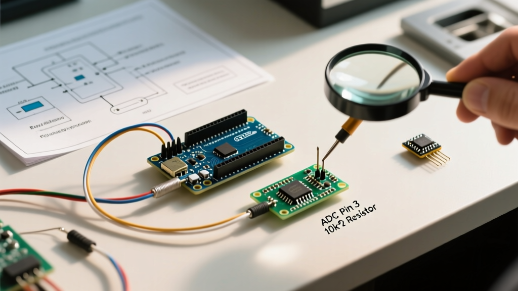
According to Arduino's official analogRead() documentation, the ATmega328P (the brain of the Uno R3 and Nano) features a 14pF internal sampling capacitor. When the ADC multiplexer connects to your pin, this capacitor must charge to the input voltage within a fraction of a microsecond. If your sensor has an output impedance greater than 10kΩ, the capacitor cannot charge fully before the conversion begins, resulting in consistently low and erratic readings.
Community-Tested Solutions for High Impedance
- The Hardware Fix (RC Snubber): Place a 100Ω series resistor followed by a 100nF X7R ceramic capacitor to ground directly at the MCU pin. This creates a low-impedance charge reservoir that isolates the ADC from the high-impedance sensor.
- The Active Buffer: For ultra-high impedance sources like piezo transducers or pH probes, the community standard is to use a rail-to-rail op-amp like the MCP6001 or the ultra-low offset OPA333 configured as a unity-gain buffer.
- The Software Delay: If you are multiplexing between multiple high-impedance pins, insert a
delayMicroseconds(50)between switching the MUX and triggering the conversion to allow the S/H capacitor to settle.
Top GitHub Libraries for ADC Noise Filtering
Raw ADC data is inherently noisy due to thermal noise and quantization error. While a simple for loop averaging 10 samples works for basic potentiometers, it introduces unacceptable latency for real-time control loops. The open-source community has developed highly optimized DSP (Digital Signal Processing) libraries specifically for AVR and ARM microcontrollers.
1. ArduinoFilters (by JonHub)
This repository is a staple for advanced makers. It provides efficient implementations of Infinite Impulse Response (IIR) and Finite Impulse Response (FIR) filters. Unlike basic averaging, an IIR Butterworth low-pass filter can smooth out 50Hz/60Hz mains hum without requiring massive sample buffers, saving precious SRAM on an ATmega328P.
2. Smoothie
For those needing adaptive filtering, the Smoothie library allows you to dynamically adjust the smoothing factor based on the rate of change of the input signal. This is heavily utilized in community-built joystick and drone throttle projects where you want to filter out hand-jitter (high frequency) but allow rapid, intentional movements (low frequency) to pass through instantly.
The ESP32 ADC Dilemma: Community Workarounds
The ESP32 revolutionized IoT, but its internal 12-bit SAR ADC is notoriously flawed. Makers migrating from the 10-bit ATmega328P often expect a clean 0-4095 range. Instead, they encounter severe non-linearity, particularly near the 0V and 3.3V rails, and massive noise floors when Wi-Fi or Bluetooth radios transmit.
"Never trust the ESP32 internal ADC for precision voltage measurement. The Wi-Fi radio draws transient current that causes ground bounce, completely destroying your ADC reference. If you need precision, use an external I2C ADC." — Consensus from the r/esp32 hardware design megathread.
As detailed in the Espressif ESP-IDF ADC Peripherals Guide, the internal ADC is uncalibrated at the factory and requires complex multi-point software calibration using the esp_adc_cal component to achieve even marginal accuracy. For 2026 projects requiring true 12-bit or higher precision, the community universally recommends bypassing the internal ADC entirely.
External ADC Showdown: 2026 Hardware Comparison
When the internal MCU ADC falls short, external ADC ICs are the answer. Below is a comparison matrix of the most popular external ADC modules championed by the maker community, balancing cost, resolution, and interface speed.
| ADC Module / IC | Resolution | Interface | Max Sample Rate | Approx. Cost (2026) | Best Community Use Case |
|---|---|---|---|---|---|
| ATmega328P (Internal) | 10-bit | Internal MUX | 15 kSPS | $0.00 (Built-in) | Potentiometers, basic LDRs |
| ADS1115 (Adafruit/TI) | 16-bit | I2C | 860 SPS | $4.50 - $6.00 | pH meters, load cells, precision DC voltage |
| MCP3208 (Microchip) | 12-bit | SPI | 100 kSPS | $2.50 - $3.50 | Audio sampling, fast multi-channel sensor arrays |
| ADS1256 (TI) | 24-bit | SPI | 30 kSPS | $12.00 - $15.00 | Seismographs, high-end laboratory scales |
For a deep dive into wiring and configuring the most popular external upgrade, the Adafruit ADS1115 Learning System Guide remains the gold standard, offering robust Python and C++ examples for differential and single-ended measurements.
Hardware Routing: Decoupling and Guard Rings
Software filters cannot fix a fundamentally compromised hardware layout. When designing custom PCBs or even wiring complex breadboards for analog inputs, EEVblog community veterans emphasize strict analog routing discipline.
- VREF Decoupling: The voltage reference pin (AREF on AVR, VREF on ARM) must be decoupled with a 100nF X7R ceramic capacitor placed as physically close to the pin as possible, supplemented by a 10µF tantalum bulk capacitor.
- Guard Rings: For high-impedance traces (like those connecting to a pH probe), route a copper "guard ring" around the analog trace. Drive this guard ring with a low-impedance buffer set to the same voltage as the analog signal. This eliminates surface leakage currents across the PCB substrate.
- Split Ground Planes: Keep digital return currents (from the MCU and motor drivers) completely separated from the analog ground plane, joining them only at a single "star ground" point directly beneath the ADC IC.
Where to Ask: The Best Forums for Analog Debugging
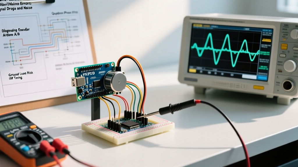
When you hit a wall with quantization noise or ground loops, these are the most active and technically rigorous communities to consult in 2026:
- EEVblog Forum (Microcontrollers & Embedded subforum): The premier destination for deep-dive hardware debugging. Expect to be asked for oscilloscope captures and schematic PDFs.
- r/AskElectronics (Reddit): Excellent for rapid feedback on breadboard layouts, component selection (e.g., choosing between an RC filter and an active op-amp), and basic ADC theory.
- Arduino Forum (Hardware & Sensors section): Best for software-specific ADC quirks, register-level manipulation of the ATmega prescaler, and library compatibility issues.
Final Thoughts on Analog Mastery
Mastering the analog input Arduino ecosystem requires looking past the analogRead() function and understanding the physics of the silicon and the PCB. By leveraging community-maintained DSP libraries, recognizing the limitations of internal SAR ADCs, and implementing proper hardware decoupling, you can elevate your microcontroller projects from noisy prototypes to reliable, production-ready instruments.