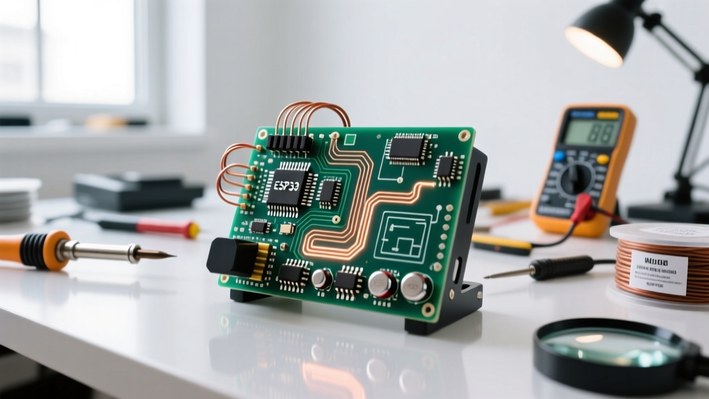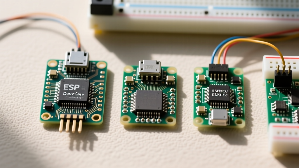

The Breadboard Dilemma: Standard ESP32 DevKit Dimensions
If you have ever tried to plug a standard ESP32 development board into a typical MB-102 solderless breadboard, you already know the frustration. Understanding exact ESP32 dimensions is critical for hardware compatibility, yet it remains one of the most overlooked aspects of early-stage prototyping. Unlike the classic Arduino Nano or ESP8266 NodeMCU, the standard ESP32 DevKitC boards often feature a wider footprint that creates severe breadboard straddling issues.
A standard solderless breadboard features a 2.54mm (0.1-inch) pin pitch and a center divider ditch that is roughly 33mm wide. The most common 30-pin ESP32-DevKitC V4 measures exactly 51.0mm in length and 28.0mm in width. When you plug this 28mm wide board across the center ditch, you are left with only 2.5mm of clearance on either side—effectively leaving just one single row of holes accessible for jumper wires on the outer power rails. If you are using a 38-pin variant, the physical width remains similar, but the increased length (54.0mm) blocks even more of the breadboard's horizontal tie-points, making it nearly impossible to plug in adjacent I2C sensors or SPI modules without resorting to a secondary breadboard.
Variant Footprint Comparison Chart
The ESP32 ecosystem has expanded far beyond the original dual-core chip. When planning your physical layout, you must account for the dimensional shifts introduced by newer architectures like the S3 and C3. Below is a precise compatibility matrix detailing the physical measurements of the most popular official and clone development boards.
| Development Board | Length (mm) | Width (mm) | Pin Count | Inner Row Spacing | Breadboard Usability |
|---|---|---|---|---|---|
| ESP32-DevKitC V4 (30-pin) | 51.0 | 28.0 | 30 | 22.86mm (0.9") | Poor (1 hole clearance) |
| NodeMCU-32S (38-pin) | 54.0 | 28.0 | 38 | 22.86mm (0.9") | Poor (Blocks power rails) |
| ESP32-S3-DevKitC-1 | 69.0 | 26.0 | 38 | 22.86mm (0.9") | Moderate (Narrower body) |
| ESP32-C3-DevKitM-1 | 35.5 | 18.0 | 18 | 15.24mm (0.6") | Excellent (Standard fit) |
| Adafruit QT Py ESP32-S3 | 22.0 | 17.8 | 14 | N/A (Edge castellation) | Requires Adapter/Feather |
As highlighted in the ESP32-DevKitC V4 Getting Started Guide, the inner row spacing of 22.86mm (0.9 inches) is a deliberate design choice to maintain compatibility with specific legacy shields, but it fundamentally breaks standard 0.1-inch grid perfboard alignment, a topic we will explore later.
Designing 3D Enclosures Around ESP32 Measurements
Transitioning from a breadboard prototype to a finished 3D-printed enclosure is where dimensional inaccuracies cause the most project failures. When modeling a case in Fusion 360 or TinkerCAD, you cannot simply use a generic 51x28mm rectangular cutout. You must account for three critical physical anomalies inherent to ESP32 development boards.
1. The USB Port Overhang
On the classic ESP32 DevKitC V4, the Micro-USB port is not perfectly flush with the PCB edge. It typically overhangs by 1.2mm to 1.5mm. If your 3D model assumes the PCB edge is the absolute zero-point for your enclosure wall, the USB cable will not seat properly, or the board will bow inward, stressing the solder joints. Conversely, many modern ESP32-S3 boards utilize surface-mount USB-C connectors that sit entirely within the 69mm length constraint. Always measure your specific board's USB overhang with digital calipers before finalizing your STL export.
2. Header Pin Height and Slop
Standard male header pins are pressed into the PCB with varying degrees of precision. On official Espressif boards, the plastic spacer of the header sits flush against the PCB, adding exactly 8.5mm of height below the board and 11.5mm above. However, on budget clone boards sourced from AliExpress or Amazon, headers are often hand-soldered at a slight 2-to-3-degree angle. To accommodate this manufacturing drift, your 3D enclosure must include a 1.5mm tolerance chamfer around the bottom pin-cutouts to prevent the plastic housing from binding against crooked headers.
3. The RF Antenna Keep-Out Zone
Perhaps the most crucial dimensional constraint is invisible. The ESP32-WROOM-32 module features a PCB trace antenna that extends to the very edge of the metal shield. According to the ESP32-WROOM-32E Datasheet, there must be a strict keep-out zone free of ground planes, copper pours, and dense plastics. If you design a 3D printed enclosure that wraps tightly around the antenna tip using Carbon Fiber-infused PLA or metallic filament, you will severely detune the antenna, dropping your Wi-Fi range from 50 meters to less than 3 meters. Always leave a minimum 5mm void space past the module's antenna edge in your CAD model.
Perfboard and PCB Integration Strategies
When moving to protoboard or perfboard, the ESP32's physical dimensions present a unique mathematical hurdle. Standard perfboard is drilled on a strict 2.54mm (0.1-inch) grid. The pins on the left and right sides of the ESP32 also follow this 2.54mm pitch vertically. However, the horizontal distance between the left and right header rows is 22.86mm (0.9 inches).
If you attempt to solder an ESP32 directly to a standard perfboard, the left pins will align perfectly to the grid, but the right pins will fall exactly between the copper pads, as 22.86mm is not a whole multiple of 2.54mm (it equals exactly 9 holes, but standard board widths usually force a 10-hole / 25.4mm span for structural integrity). To solve this, hardware engineers use one of two workarounds:
- The Offset Solder Technique: Solder the left headers perfectly straight, but intentionally angle the right headers outward by 1mm at the top, allowing the pins to bend slightly and reach the next available copper pad.
- Custom Breakout PCBs: Design a simple 2-layer carrier board in KiCad that routes the 0.9-inch spacing out to a standard 1.0-inch (25.4mm) DIP width, mimicking the footprint of an ATmega2560 or standard Arduino Uno shield layout.
Clone Board Dimensional Drift: A Warning for Makers
It is vital to understand that "ESP32 dimensions" are only strictly standardized at the silicon and bare-module level. The ESP32-S3-DevKitC-1 User Guide provides exact PCB outlines for the official reference design, but third-party manufacturers frequently alter the board length by 2mm to 4mm to accommodate larger voltage regulators (like the AMS1117 vs. the ME6211) or to add secondary RGB LEDs. If you are designing a commercial product or a precise acrylic laser-cut enclosure, never base your CAD files on generic internet diagrams. Always purchase the exact batch of development boards you intend to use, measure three random samples with Mitutoyo calipers, and average the dimensions to account for batch-to-board manufacturing tolerances.
Module vs. Development Board: Shrinking the Footprint
When your project graduates from a messy breadboard to a permanent installation, the bulky dimensions of the development board become a liability. The bare ESP32-WROOM-32E module itself measures a mere 18.0mm x 25.5mm x 3.1mm. By designing a custom PCB that accepts the bare module (or utilizing surface-mount castellation pads), you reduce the overall footprint by over 60% compared to the DevKitC. This massive reduction in physical dimensions allows for integration into wearable tech, compact IoT sensor nodes, and retro-fitted smart home switches where every cubic millimeter of internal volume is fiercely contested. Remember, however, that transitioning to the bare module requires you to manually design the 3.3V LDO voltage regulation, USB-to-UART bridge circuitry, and auto-reset transistor logic that the development board previously handled for you.
Summary: Measure Twice, Print Once
Mastering ESP32 dimensions is about more than just knowing the length and width of a green circuit board. It requires a holistic understanding of pin pitch anomalies, USB overhang tolerances, RF keep-out zones, and the physical realities of solderless prototyping. By referencing exact datasheet measurements and accounting for clone-board manufacturing drift, you can eliminate the friction between your digital CAD designs and your physical hardware deployments, ensuring your enclosures fit perfectly and your antennas broadcast at maximum efficiency.