
When transitioning from basic LED blinking to building CNC plotters, 3D printers, or automated camera sliders, controlling precise rotational movement becomes essential. This is where the arduino stepper motor driver ecosystem comes into play. While an Arduino microcontroller is brilliant at logic and timing, its GPIO pins cannot source the continuous current required to drive the inductive coils of a bipolar stepper motor. Attempting to do so will instantly fry your microcontroller's ATmega328P chip.
A stepper motor driver acts as the crucial bridge: it takes low-power logic signals (STEP and DIR) from your Arduino and translates them into high-current, sequenced pulses that energize the motor coils. However, the market is flooded with options, and beginners frequently fall into traps like skipping current calibration or ignoring decoupling capacitors, leading to melted wires and dead drivers. This guide provides a comprehensive, real-world framework for selecting, wiring, and programming the right driver for your project.
The Hardware Decision Matrix: A4988 vs. DRV8825 vs. TMC2209
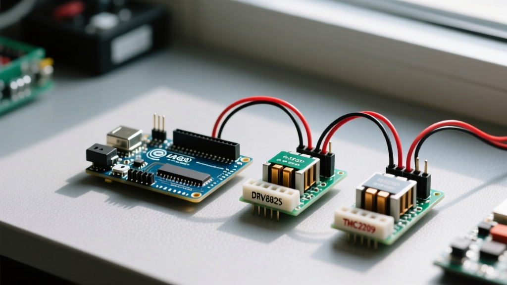
For 90% of beginner and intermediate DIY motion control projects, your choice will come down to three main carrier boards. Each utilizes a different silicon chip but shares a similar physical footprint (often based on the original Pololu carrier design).
| Feature | A4988 (Allegro) | DRV8825 (TI) | TMC2209 (Trinamic) |
|---|---|---|---|
| Max Continuous Current | 1.5A (with heatsink) | 2.2A (with heatsink & cooling) | 2.0A (RMS) / 2.8A (Peak) |
| Max Microstepping | 1/16 | 1/32 | 1/256 (Interpolated) |
| Noise Profile | Audible whine at low speeds | Loud, harsh buzzing | Virtually silent (StealthChop2) |
| Advanced Interfaces | None (Hardware pins only) | None (Hardware pins only) | UART (Serial tuning, StallGuard) |
| Typical Price (2024) | $2.50 - $4.00 | $3.50 - $5.50 | $8.00 - $14.00 |
| Best Use Case | Basic prototyping, low-budget builds | Higher torque NEMA 17 motors | Desktop CNCs, audio-sensitive environments |
For pure beginners on a strict budget, the A4988 Stepper Motor Driver Carrier remains the gold standard for learning. However, if your project will sit on a desk near you (like a pen plotter), the acoustic noise of the A4988 and DRV8825 will quickly become maddening. Upgrading to a TMC2209 driver is highly recommended for any desktop application.
Wiring the A4988 to an Arduino Uno
Before writing a single line of code, you must wire the driver correctly. The standard carrier board features two distinct power domains: Logic (VDD) and Motor Power (VMOT). Mixing these up or ignoring the ground references is the number one cause of dead Arduino boards.
The Decoupling Capacitor Rule
Critical Warning: You must place a 100µF electrolytic capacitor across the VMOT and GND pins on the driver board. Stepper motors generate massive inductive voltage spikes when the internal H-bridge switches off. Without this capacitor to absorb the spike, the voltage will arc back into the driver chip, permanently destroying the MOSFETs. Always observe correct polarity (the stripe on the capacitor goes to GND).
Pinout and Connections
- VMOT: Connect to your external power supply positive (typically 8V to 35V for NEMA 17 motors). Do not use the Arduino's 5V rail for motor power.
- GND: Connect to the external power supply ground AND the Arduino GND. A common ground is mandatory for the logic signals to be read correctly.
- VDD: Connect to the Arduino 5V pin (powers the internal logic of the driver chip).
- STEP: Connect to any digital pin on the Arduino (e.g., Pin 3). Every rising edge on this pin moves the motor one microstep.
- DIR: Connect to any digital pin (e.g., Pin 2). HIGH = Clockwise, LOW = Counter-Clockwise.
- 1A, 1B, 2A, 2B: Connect to the four wires of your bipolar stepper motor. (Use a multimeter in continuity mode to find the two coil pairs before wiring).
The VREF Calibration Trap
Beginners often plug in the power, upload code, and wonder why their motor is stuttering, missing steps, or why the driver chip is burning hot to the touch. This happens because the current limit potentiometer on the driver board is set to a random factory default.
You must calibrate the VREF (Reference Voltage) to match your specific motor's rated current. For a standard A4988 board with a 0.100Ω sense resistor, the formula is:
VREF = Current Limit × 8 × Rcs
If you have a standard NEMA 17 motor rated for 1.0A per phase, your target VREF is: 1.0 × 8 × 0.100 = 0.8V.
How to Measure and Set VREF
- Power only the logic side (connect Arduino USB, but leave VMOT motor power disconnected).
- Set your digital multimeter to DC Voltage (20V range).
- Place the black probe on the Arduino GND or the driver's GND pin.
- Place the red probe gently on the metal shaft of the tiny brass potentiometer on the driver board (or the TP1 test point if available).
- Using a ceramic or plastic trim tool (never metal, to avoid shorting), turn the potentiometer clockwise to increase voltage, or counter-clockwise to decrease it until your multimeter reads exactly 0.8V.
Writing Smooth Motion Code with AccelStepper
While you can use basic digitalWrite() and delayMicroseconds() to pulse the STEP pin, this approach lacks acceleration. If you command a stepper motor to instantly jump from 0 to 1000 steps per second, the rotor's inertia will cause it to stall and vibrate violently. You must ramp the speed up and down.
Instead of writing complex timing loops, use the industry-standard AccelStepper Library by Mike McCauley. It handles non-blocking acceleration, deceleration, and multi-motor coordination flawlessly.
#include <AccelStepper.h>

// Define pins
const int stepPin = 3;
const int dirPin = 2;

// Initialize AccelStepper (1 = Driver interface with STEP/DIR pins)
AccelStepper myMotor(1, stepPin, dirPin);

void setup() {
  // Set maximum speed in steps per second
  myMotor.setMaxSpeed(1000);

  // Set acceleration in steps per second per second
  myMotor.setAcceleration(500);

  // Move 6400 steps (assuming 1/16 microstepping on a 200 step/rev motor = 2 full revolutions)
  myMotor.moveTo(6400);
}

void loop() {
  // The run() function must be called continuously in the loop
  // It calculates the required speed and handles the STEP pulses
  myMotor.run();

  // Optional: Reverse direction when target is reached
  if (myMotor.distanceToGo() == 0) {
    myMotor.moveTo(-myMotor.currentPosition());
  }
}
Real-World Failure Modes and Diagnostics
Even with perfect wiring and code, physical mechanics and electrical quirks can cause issues. Here is a diagnostic framework for the most common beginner failure modes:
1. Motor Vibrates Violently but Doesn't Rotate
- Cause A (Software): Your starting speed or max speed is too high for the motor's torque curve, and it is stalling. Lower the
setMaxSpeed()value or increasesetAcceleration()to give it a gentler ramp-up. - Cause B (Hardware): The coil pairing is wrong. If you mixed up the wires from Coil 1 and Coil 2 (e.g., wired 1A, 2A, 1B, 2B), the magnetic fields will fight each other. Re-check coil continuity with a multimeter.
2. The Driver Chip is Scalding Hot
The A4988 and DRV8825 will shut down via thermal protection if they exceed ~165°C. If you cannot keep your finger on the chip for more than a second, it is too hot.
- Fix 1: Re-check your VREF. You may have accidentally set it to 1.5V, pushing way too much current through the motor.
- Fix 2: Attach a stick-on aluminum heatsink and point a small 5V brushless fan directly at the driver board. Active cooling allows the DRV8825 to push closer to its 2.2A limit safely.
3. Missed Steps During High-Speed Travel
If your CNC plotter draws curved lines as straight, jagged angles, your motor is missing steps under load.
- Fix: Increase the voltage supplied to VMOT. Stepper motors lose torque at high speeds due to coil inductance. Pushing 24V into VMOT (instead of 12V) forces the current to ramp up faster in the coils, maintaining high-speed torque. Just ensure your driver's maximum voltage rating is not exceeded.
Mastering the arduino stepper motor driver is a rite of passage for DIY electronics enthusiasts. By respecting the electrical boundaries, calibrating your current limits properly, and leveraging robust libraries like AccelStepper, you will build motion systems that are reliable, precise, and ready for real-world automation.