
The Maker's Shift: Why Arduino LiDAR is Taking Over
For years, the Arduino community relied heavily on ultrasonic sensors like the HC-SR04 for distance measurement. While cheap and easy to use, they suffer from wide beam angles, temperature drift, and acoustic blind spots. Enter Arduino LiDAR integration. Time-of-Flight (ToF) optical sensors have plummeted in price over the last few years, making millimeter-accurate, narrow-beam distance sensing accessible for rover navigation, drone altimetry, and DIY SLAM (Simultaneous Localization and Mapping). This community resource synthesizes field-tested wiring diagrams, protocol breakdowns, and failure modes gathered from thousands of maker hours to help you bypass the common pitfalls of optical ToF sensors.
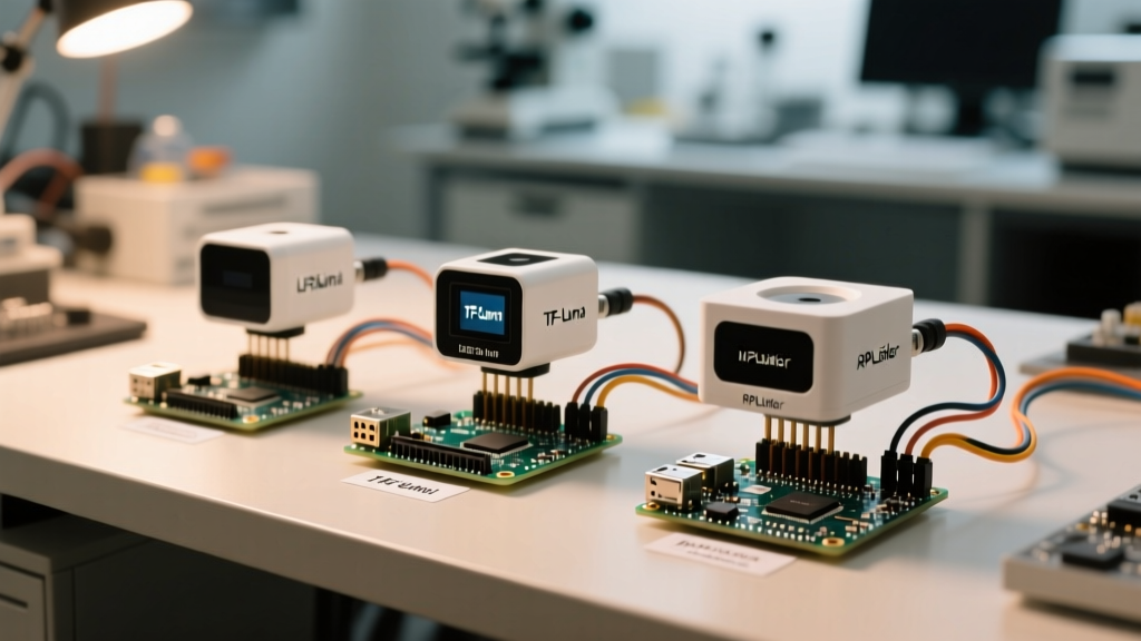
Community Sensor Showdown: TF-Luna vs. TFmini Plus vs. RPLidar A1
Choosing the right sensor depends entirely on your environment, budget, and processing overhead. Below is a breakdown of the three most popular LiDAR modules discussed in maker forums and robotics communities.
| Sensor Model | Max Range | Interface | Avg Price | Best Community Use Case |
|---|---|---|---|---|
| Benewake TF-Luna | 8m | UART / I2C | $12 | Indoor rover obstacle avoidance, budget projects |
| Benewake TFmini Plus | 12m | UART / I2C | $45 | Outdoor drones, IP65 environments, high ambient light |
| Slamtec RPLidar A1 | 12m (360°) | UART (USB Bridge) | $99 | 2D SLAM mapping, ROS integration, autonomous mowers |
The TF-Luna is the undisputed king of budget 1D LiDAR. It uses an 850nm VCSEL laser and is incredibly lightweight (2.5g). However, it struggles in direct sunlight. The TFmini Plus upgrades the internal processing, offering better ambient light rejection and an IP65 rating, making it the community standard for outdoor robotics. For 360-degree mapping, the RPLidar A1 remains the entry-level standard, though it requires significantly more mechanical and electrical overhead.
Hardware Integration: Avoiding the 5V Logic Trap
The most common point of failure in Arduino LiDAR projects is ignoring logic-level thresholds. Most modern LiDAR modules, including the Benewake lineup, operate strictly at 3.3V logic.
The TX/RX Voltage Mismatch
If you are using a 5V Arduino (like the Uno or Mega), the LiDAR's TX pin outputs 3.3V. The ATmega328P microcontroller requires a minimum of 0.6 × Vcc (which equals 3.0V) to reliably read a HIGH signal. While 3.3V technically crosses this threshold, it leaves almost zero noise margin. A slightly loose wire or long cable run will result in dropped UART frames. Furthermore, if your Arduino transmits a 5V signal from its TX pin directly into the LiDAR's 3.3V RX pin, you will permanently damage the sensor's UART receiver.
- Best Practice: Use a bidirectional logic level converter (like the BSS138 MOSFET-based modules) between the Arduino and the LiDAR.
- Alternative: Migrate to a native 3.3V microcontroller, such as the Arduino Nano 33 IoT, Teensy 4.0, or ESP32, which interfaces with 3.3V LiDARs natively.
Power Decoupling and Brownouts
LiDAR modules draw peak current during laser firing or motor spin-up. The TFmini Plus, for example, can spike to 140mA. If you are powering the sensor directly from the Arduino's 3.3V LDO regulator, this spike can cause a localized voltage droop, resetting the sensor or corrupting serial data. The community consensus is to solder a 220µF electrolytic capacitor and a 0.1µF ceramic capacitor in parallel across the VCC and GND pins as close to the sensor header as possible.
Decoding the 9-Byte UART Frame
Unlike simple pulse-width sensors, UART LiDARs stream continuous data packets. The Benewake protocol uses a 9-byte frame structure. Understanding this structure is critical for writing robust, non-blocking parsing code.
- Byte 0 & 1 (Header): Always
0x59 0x59(ASCII 'Y'). Used to sync the stream. - Byte 2 & 3 (Distance): Distance in centimeters. Byte 2 is the low byte, Byte 3 is the high byte (Little Endian).
- Byte 4 & 5 (Strength): Signal strength/quality. Crucial for filtering out bad reads.
- Byte 6 (Integration Time): Exposure time of the sensor (varies by model).
- Byte 7 (Checksum): The sum of Bytes 0 through 6, masked with
0xFF. - Byte 8 (Reserved/End): Usually
0x00or a secondary status flag.
When writing your Arduino sketch, avoid using delay() or blocking functions. Instead, implement a state machine that reads one byte at a time via Serial.available(), checking for the 0x59 header before buffering the remaining 7 bytes. For official library implementations, refer to the Benewake TFmini Plus Arduino GitHub repository.
Software Implementation & Buffer Management
A frequent issue raised in community forums is serial buffer overflow, especially when using SoftwareSerial on an Arduino Uno. The SoftwareSerial library disables interrupts while transmitting or receiving, which can cause you to miss bytes from the LiDAR if your sketch is simultaneously updating an LCD display or reading encoders.
Community Tip: If you must use a 5V Arduino without multiple hardware serial ports, use the Arduino SoftwareSerial documentation to understand baud rate limits. Alternatively, switch to the
AltSoftSeriallibrary, which uses hardware timers and is far more reliable at the 115200 baud rate required by 360-degree LiDARs like the RPLidar A1.
For 2D mapping with the RPLidar, the data volume is too high for an 8-bit AVR microcontroller to handle natively. The community standard is to use an ESP32 or a Raspberry Pi Pico to ingest the Slamtec RPLidar SDK data, filter the point cloud, and send simplified coordinate arrays to the Arduino via I2C or secondary UART.
Real-World Failure Modes & Field Troubleshooting
Even with perfect wiring, optical LiDARs are subject to environmental physics. Here are the most common failure modes and how to mitigate them in your code and hardware design.
1. IR Saturation in Direct Sunlight
Sunlight contains massive amounts of infrared radiation. The 850nm VCSEL laser in the TF-Luna can be completely washed out by direct sunlight, causing the sensor to report a distance of 0 or max out at 1200cm. Fix: Use the TFmini Plus for outdoor applications, as it features a narrower optical bandpass filter and higher laser power. In code, monitor the 'Strength' bytes; if strength drops below 100, flag the reading as invalid and rely on ultrasonic fallbacks.
2. Multi-Path and Glossy Surface Reflections
LiDAR assumes light travels in a straight line and bounces directly back. If you scan a glossy black surface or a mirror at an angle, the laser beam can reflect away from the receiver, or bounce around a room before returning (multi-path). This results in phantom obstacles. Fix: Implement a rolling median filter in your Arduino sketch. Taking the median of 5 rapid consecutive readings will eliminate sudden, physically impossible spikes caused by specular reflections.
3. Baud Rate Drift and Garbage Data
If your serial monitor is printing random characters or negative distances, your baud rate is likely mismatched. While the Benewake sensors default to 115200 baud, some community forks and older TFmini models default to 9600. Fix: Use the official Benewake PC GUI tool via a USB-to-TTL adapter to verify and lock the sensor's baud rate before integrating it into your robot's harness.