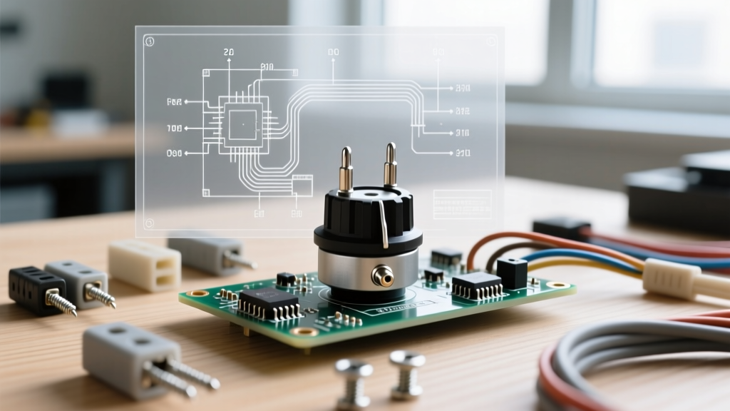

The Role of Potentiometers in Appliance Speed Control
When repairing household appliances like stand mixers, sewing machines, or variable-speed routers, understanding the potentiometer wiring diagram is critical for restoring precise motor control. Unlike simple on/off switches, a potentiometer (often abbreviated as a 'pot') acts as a variable resistor or voltage divider, allowing the user to dial in exact operational speeds or heating levels. In modern appliance repair, replacing a faulty speed-control dial requires more than just swapping parts; it requires a firm grasp of terminal identification, taper selection, and safety configurations to prevent catastrophic motor runaway.
Anatomy of a 3-Terminal Appliance Potentiometer
Before consulting any wiring schematic, you must understand the physical layout of the component. A standard 3-terminal potentiometer consists of a resistive track (made of carbon composition, cermet, or conductive plastic) and a sliding contact known as the wiper.
Terminal Identification and Taper Selection
- Terminal 1 (CCW): The counter-clockwise end of the resistive track. In most appliance dials, this represents the 'Off' or 'Lowest Speed' position.
- Terminal 2 (Wiper): The middle terminal connected to the sweeping contact. This is the output terminal that delivers the variable resistance or divided voltage to the appliance's control board or TRIAC gate.
- Terminal 3 (CW): The clockwise end of the track, representing the 'Maximum Speed' or 'High' position.
Appliance manufacturers almost exclusively use linear taper potentiometers (marked with a 'B' on the casing, such as B500) for motor speed control. Audio or logarithmic tapers (marked with an 'A') are reserved for audio equipment and will result in highly erratic, non-linear speed jumps if used in a KitchenAid mixer or Singer sewing machine.
Step-by-Step Potentiometer Wiring Diagram & Guide
In appliance circuitry, a 3-terminal pot is typically wired in one of two configurations: as a rheostat (variable resistor) or as a voltage divider. The correct configuration depends entirely on whether the pot is handling the motor load directly (older appliances) or sending a reference signal to a microcontroller/TRIAC (modern appliances).
The Rheostat Configuration (Direct Series Control)
In older sewing machines or heavy-duty fans, the potentiometer is wired in series with the motor to drop voltage directly. To wire this safely, you must use a 'fail-safe' rheostat configuration.
- Connect the AC Hot Line (from the power cord) to Terminal 1.
- Connect Terminal 2 (Wiper) to the Motor Input.
- Critical Safety Step: Jump a small wire from Terminal 2 to Terminal 3.
Why the jumper? If the wiper loses contact with the carbon track due to vibration or wear, a standard 2-terminal rheostat wiring would create an open circuit, killing the motor. However, in certain TRIAC-based phase control circuits, an open wiper can cause the TRIAC to latch into full conduction, sending the appliance to maximum speed dangerously. Tying Terminal 3 to the Wiper ensures that if the wiper lifts, the circuit defaults to maximum resistance (safest state) rather than an unpredictable open state.
The Voltage Divider Configuration (Logic & TRIAC Control)
Modern appliances, such as the KitchenAid KSM150 series or electronic soldering stations, use the potentiometer to feed a low-voltage DC reference to a control board. The board then fires a TRIAC to control the AC motor.
- Connect Terminal 1 to Ground (GND) on the control PCB.
- Connect Terminal 3 to the Reference Voltage (VCC), typically 5V DC.
- Connect Terminal 2 (Wiper) to the Analog Input / Gate Trigger pin on the PCB.
WARNING: Never confuse the high-voltage AC rheostat wiring with low-voltage DC logic wiring. Applying 120V/240V AC mains directly to a PCB voltage divider input will instantly destroy the microcontroller and create a severe shock and fire hazard. Always trace the PCB copper pours to verify ground planes before soldering.
Common Appliance Applications and Resistance Values
Selecting the correct replacement potentiometer requires matching not just the physical footprint, but the exact resistance and wattage rating. Using a 0.5W pot in a 5W circuit will result in the carbon track burning out within minutes of operation.
| Appliance Type | Typical Pot Resistance | Taper Type | Wattage Rating | Common Failure Mode |
|---|---|---|---|---|
| Stand Mixer (e.g., KitchenAid) | 470Ω - 1kΩ | Linear (B) | 2W - 5W | Carbon track wear causing speed surging |
| Sewing Machine Foot Pedal | 500Ω - 5kΩ | Linear / Custom | 5W+ (Wirewound) | Mechanical spring fatigue, wiper lift |
| Soldering Station (e.g., Hakko) | 250Ω - 1kΩ | Linear (B) | 0.5W - 1W | Flux ingress causing dead spots |
| Router / Woodworking Tool | 10kΩ - 50kΩ | Linear (B) | 0.5W (Logic Level) | Dust ingress causing erratic speed drops |
Troubleshooting: Diagnosing a Failing Appliance Potentiometer
Before desoldering or cutting wires, verify the failure using a digital multimeter (DMM). According to Fluke's official testing guidelines, measuring resistance while the component is still connected to the circuit can yield false readings due to parallel paths on the PCB. Always isolate at least one terminal of the potentiometer before testing.
Multimeter Testing Procedure
- Total Resistance Check: Set your DMM to the Ohms (Ω) setting. Place probes on Terminal 1 and Terminal 3. The reading should match the rated value of the pot (e.g., ~1000Ω for a 1k pot) within a 10% tolerance. If it reads infinite (OL), the internal track is snapped.
- Wiper Sweep Test: Move one probe to Terminal 2 (Wiper). Slowly rotate the appliance dial from minimum to maximum. The resistance should climb smoothly and linearly. Any sudden jumps to 'OL' or erratic drops indicate a 'dead spot' caused by carbon dust buildup or physical gouging of the track.
- Grounding Verification: Check for continuity between the metal casing of the potentiometer and the appliance chassis ground. In metal-bodied pots used in AC appliances, the casing must be grounded to prevent the user from receiving a shock if internal insulation fails.
Soldering vs. Crimping: Best Practices for Appliance Repair
Appliances generate significant mechanical vibration and thermal cycling. The method you use to terminate wires to the potentiometer lugs will dictate the lifespan of your repair.
When to Solder
Soldering is mandatory for PCB-mounted potentiometers and low-voltage logic connections. Use a rosin-core solder (60/40 leaded is preferred for DIY appliance repair due to its lower melting point and superior wetting, or SAC305 for RoHS compliance). Set your soldering iron to 350°C for leaded and 380°C for lead-free. Pro Tip: Always use a heat-sink clip on the terminal lug when soldering near the potentiometer casing to prevent melting the internal plastic bobbin that holds the carbon track.
When to Crimp
For heavy-duty, high-voltage AC connections (like the mains input on a sewing machine foot pedal), soldering can become brittle over years of vibration. Instead, use high-temperature spade connectors with a proper ratcheting crimper. Apply a thin layer of dielectric grease to the spade connector before pushing it onto the pot's lug to prevent oxidation and ensure a gas-tight mechanical connection.
Advanced Insights: Phase Control and TRIAC Interaction
For technicians diving deeper into appliance electronics, it is vital to understand how the potentiometer interacts with the TRIAC. As detailed in comprehensive electrical theory resources like All About Circuits, a potentiometer alone cannot handle the high current of a universal motor. Instead, the pot forms an RC (resistor-capacitor) timing network.
By adjusting the resistance, you alter the time it takes for a capacitor to charge to the DIAC's breakover voltage. This, in turn, dictates the phase angle at which the TRIAC fires during each AC half-cycle. If you replace a 1kΩ pot with a 5kΩ pot 'just to make it fit,' you will drastically alter the RC time constant. The result? The dial will have no effect for the first 80% of its rotation, and then suddenly surge to full speed in the final 20%, rendering the appliance unusable and potentially dangerous. Always match the exact OEM resistance specification.
Final Thoughts on Appliance Wiring Safety
Mastering the potentiometer wiring diagram bridges the gap between basic component replacement and true electromechanical troubleshooting. Whether you are restoring a vintage Singer sewing machine or fixing a modern stand mixer's speed control board, respecting the taper, wattage, and fail-safe wiring configurations will ensure your repair is both functional and safe. For further reading on resistor networks and variable components, Electronics Tutorials offers excellent foundational theory that applies directly to appliance circuit analysis.