
The Core Question: What Is the Frequency of the Alternating Current?
When electrical professionals and DIYers ask, what is the frequency of the alternating current, the textbook answer is straightforward: it is the number of complete sine wave cycles that occur per second, measured in Hertz (Hz). In North America, the standard grid frequency is 60 Hz, while most of Europe, Asia, and Africa operate at 50 Hz. However, in the field of electrical troubleshooting, the textbook answer is only the baseline. Real-world AC frequency is a dynamic, living metric that fluctuates based on mechanical load, grid stability, and power electronics.
Understanding AC frequency from a troubleshooting perspective requires looking beyond the nominal 60 Hz or 50 Hz label. Frequency dictates the synchronous speed of AC motors, the magnetic flux density in transformers, and the timing of control circuits. When frequency drifts, equipment fails. This guide dives deep into the diagnostic procedures, failure modes, and corrective actions required when AC frequency deviates from its nominal baseline.
The Physics of Failure: The Volts-Per-Hertz (V/Hz) Ratio
You cannot troubleshoot AC frequency without understanding the Volts-per-Hertz (V/Hz) ratio. This fundamental principle governs the magnetic flux in the iron cores of motors and transformers. The formula is simple: V/Hz = Voltage / Frequency.
For a standard 460V, 60 Hz industrial motor, the nominal V/Hz ratio is 7.67. The motor's iron core is designed to handle exactly this amount of magnetic flux. If the frequency drops to 55 Hz due to a struggling standby generator, but the voltage remains at 460V, the V/Hz ratio spikes to 8.36. This over-fluxes the motor core, leading to magnetic saturation. The result? Massive eddy current losses, severe overheating, and eventual insulation breakdown, even if the motor is running under a light mechanical load.
Expert Troubleshooting Tip: Never assume a motor is safe just because the voltage reads correctly on your multimeter. If the NEMA MG-1 Standard tolerance for frequency (typically ±5%) is violated, the V/Hz ratio will push the motor into thermal failure long before the overload relay trips.
Diagnostic Toolkit: Measuring Frequency in the Field
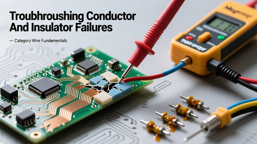
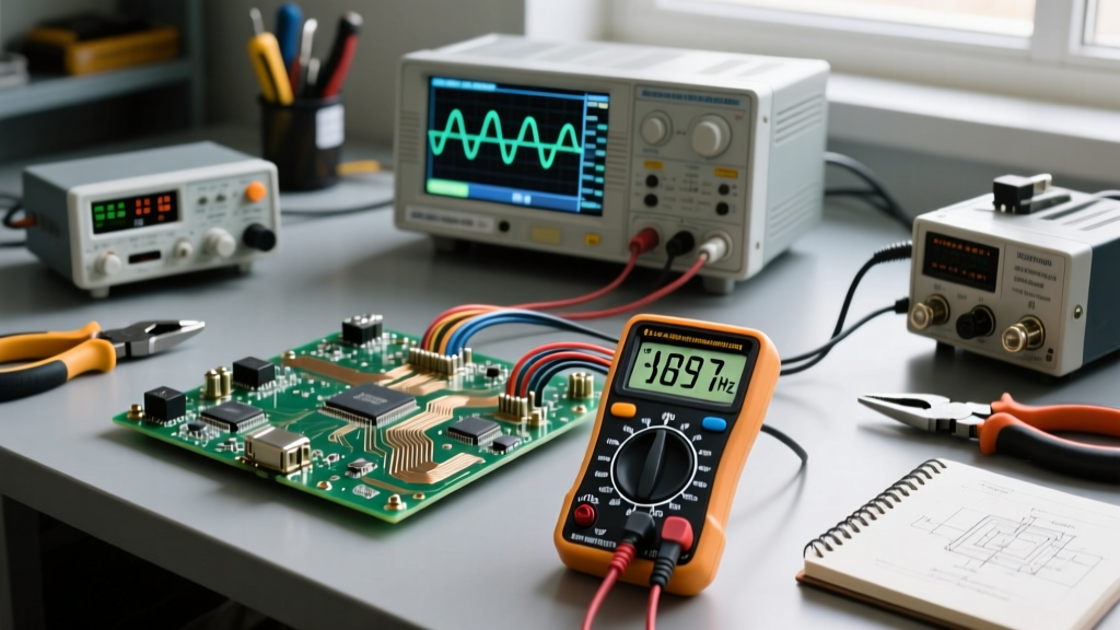
Answering 'what is the frequency of the alternating current' requires the right diagnostic equipment. Standard digital multimeters (DMMs) calculate frequency by detecting the zero-crossing points of the AC waveform. This works perfectly for clean utility grid power, but it fails catastrophically in modern industrial environments.
1. True-RMS Multimeters with Low-Pass Filters
When measuring the output of a Variable Frequency Drive (VFD), the waveform is not a clean sine wave; it is a Pulse Width Modulated (PWM) square wave with a high-frequency carrier signal (often 2 kHz to 15 kHz). A standard DMM will read the carrier frequency, not the fundamental motor frequency. You must use a meter like the Fluke 87V, which features a dedicated low-pass filter to block the PWM carrier and accurately display the fundamental AC frequency.
2. Power Quality Analyzers (PQAs)
For grid-level troubleshooting, a PQA (such as the Fluke 435 II) is mandatory. PQAs do not just display instantaneous frequency; they log frequency drift over time, capturing micro-hertz variations that indicate utility grid instability, load shedding events, or harmonic distortion.
Troubleshooting Common Frequency Anomalies
When you verify that the frequency has drifted outside the acceptable ±0.5 Hz tolerance for sensitive electronics or ±3 Hz for heavy machinery, you must isolate the root cause. Here are the three most common frequency anomalies and how to troubleshoot them.
Scenario A: Standby Generator Frequency Droop
The Symptom: A facility's 60 Hz standby generator drops to 57 Hz when a large HVAC compressor kicks on. Lights flicker, and UPS systems trigger alarms.
The Root Cause: Generator frequency is directly tied to the mechanical RPM of the prime mover (the diesel or natural gas engine). A 4-pole generator must spin at exactly 1800 RPM to produce 60 Hz. When a massive electrical load is applied, the magnetic resistance inside the alternator increases, physically slowing the engine down. If the engine's mechanical governor cannot inject fuel fast enough to compensate, the RPM drops, and so does the frequency.
The Fix: Troubleshoot the mechanical governor linkage for binding. Check the fuel filters for restriction. If the mechanical system is sound, the generator may be undersized for the step-load, requiring the installation of a soft-start VFD on the HVAC compressor to reduce the inrush current.
Scenario B: VFD Harmonic Distortion and Ghost Frequencies
The Symptom: A motor driven by a VFD runs erratically, overheats, and the VFD display shows a stable 60 Hz, but a portable oscilloscope shows massive waveform distortion.
The Root Cause: Long cable runs between the VFD and the motor act as antennas, reflecting high-frequency PWM pulses back to the drive (standing waves). This creates harmonic distortion that corrupts the fundamental frequency waveform, confusing the motor's magnetic field.
The Fix: Install a dV/dt filter or a sine wave filter at the VFD output. Ensure the VFD carrier frequency is tuned down (e.g., from 8 kHz to 4 kHz) to reduce capacitive coupling in the cable, and verify that the motor is inverter-duty rated to handle the voltage spikes.
Scenario C: Grid Instability and Transformer Saturation
The Symptom: In regions with weak utility grids, the incoming AC frequency may chronically operate at 59.2 Hz instead of 60 Hz. Facility transformers emit a loud, abnormal hum and run unusually hot.
The Root Cause: As mentioned in the V/Hz ratio section, a lower frequency with a constant utility voltage forces the transformer core into saturation. The loud hum is the physical result of magnetostriction—the iron core physically expanding and contracting violently as it is over-magnetized.
The Fix: You cannot fix the utility grid. Instead, you must install an automatic tap-changing transformer or a buck-boost transformer setup to lower the incoming voltage proportionally to the frequency drop, restoring the safe V/Hz ratio.
Frequency vs. Voltage: The Troubleshooting Matrix
Use this diagnostic matrix to quickly cross-reference your multimeter readings with likely failure modes in AC systems.
| Measured State | Frequency Reading | Voltage Reading | Probable Root Cause | Corrective Action |
|---|---|---|---|---|
| Severe Droop | 54 Hz - 57 Hz | Low (e.g., 410V) | Generator prime mover overload; severe mechanical governor lag. | Shed non-critical loads; service engine fuel delivery system. |
| Mild Drift | 59.0 Hz - 59.5 Hz | Normal (e.g., 460V) | Utility grid instability; regional generation deficit. | Monitor UPS battery health; adjust transformer taps if possible. |
| VFD Output Error | Erratic / 2kHz+ | Normal DC Bus | Multimeter reading PWM carrier wave instead of fundamental. | Enable low-pass filter on DMM; use PQA for accurate reading. |
| Over-Speed | 61 Hz - 63 Hz | High (e.g., 490V) | Generator governor hunting; utility capacitor bank over-correction. | Recalibrate generator PID controller; check utility power factor. |
Real-World Failure Modes: The Cost of Ignoring Frequency
Ignoring AC frequency anomalies is a costly mistake. Consider the case of a marine vessel transitioning from a 60 Hz shore power connection to its onboard 50 Hz generators. If the crew fails to adjust the VFD parameters or swap the motor pulleys, a 60 Hz motor running on 50 Hz will operate at 83% of its designed speed. To maintain the same mechanical output (horsepower), the motor must draw significantly more current. Combined with the reduced cooling from the slower-spinning shaft-mounted fan, the motor windings will bake, leading to a dead short to ground within hours.
Furthermore, modern Department of Energy monitored grid systems rely on precise frequency to synchronize distributed energy resources (DERs) like solar inverters. If the local grid frequency drifts beyond the inverter's programmed anti-islanding thresholds (usually 59.3 Hz to 60.5 Hz), the inverter will instantly disconnect to protect utility workers. Troubleshooting a 'dead' solar array often boils down to verifying that the local utility frequency hasn't nudged the inverter into a protective shutdown.
Summary: Beyond the Textbook Answer
So, what is the frequency of the alternating current? It is the heartbeat of your electrical system. While 60 Hz or 50 Hz is the nominal target, the true answer is whatever your diagnostic equipment measures at the point of use. By mastering the V/Hz ratio, utilizing low-pass filtered diagnostic tools, and understanding the mechanical roots of generator droop, you can troubleshoot AC frequency issues before they result in catastrophic equipment failure. Always adhere to NEMA and IEEE standards when evaluating frequency tolerances, and never trust a nominal label when a True-RMS meter tells a different story.