
What Exactly is Alternating Current (AC)?
Before diving into the specific sources of alternating current, we need to establish what AC actually is. Unlike Direct Current (DC), where electrons flow continuously in a single direction from the negative to the positive terminal, Alternating Current (AC) periodically reverses its direction. In North America, this reversal happens 60 times per second (60 Hz), while in Europe and many other parts of the world, it occurs 50 times per second (50 Hz).
This oscillation creates a sine wave when viewed on an oscilloscope. The ability of AC to easily step up and step down voltages via transformers is the primary reason it won the 'War of the Currents' in the late 19th century, championed by Nikola Tesla over Thomas Edison's DC systems. But where does this oscillating power actually come from?
The Core Physics: How AC is Generated
Almost all grid-scale sources of alternating current rely on a fundamental principle of physics discovered by Michael Faraday in 1831: Electromagnetic Induction. According to Faraday's Law of Induction, a changing magnetic field within a closed loop of wire induces an electromotive force (EMF), or voltage, across the wire.
In a standard AC generator (alternator), this is achieved using two main components:
- The Rotor: The rotating electromagnet that creates the moving magnetic field.
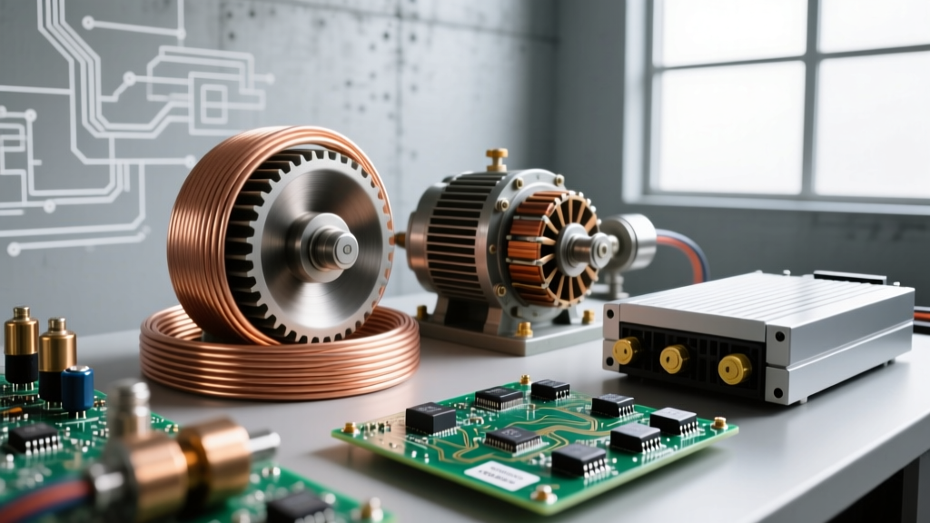
- The Stator: The stationary outer shell containing tightly wound copper wire coils.
As the rotor spins, its magnetic poles (North and South) alternately sweep past the stator windings. This continuous cutting of magnetic flux lines forces the electrons in the stator wire to move back and forth, naturally producing an alternating sine wave. Unlike DC generators that use a split-ring commutator to force current in one direction, AC generators use continuous slip rings to allow the naturally alternating current to flow out to the circuit.
Primary Mechanical Sources of Alternating Current
The vast majority of the world's electricity is generated by spinning massive turbines connected to synchronous alternators. The U.S. Energy Information Administration (EIA) notes that mechanical rotation remains the backbone of global power generation. Here are the primary mechanical sources:
1. Hydroelectric Turbines (The Heavyweights)
Hydroelectric dams use the potential energy of falling water to spin massive Francis or Kaplan turbines. Because water flows at relatively low speeds compared to steam, hydroelectric generators typically feature salient pole rotors with a high number of magnetic poles (often 40 to 80). This allows them to generate 60 Hz AC power at much lower rotational speeds (e.g., 90 to 180 RPM), perfectly matching the grid's frequency requirements without the need for complex gearing.
2. Thermal Power Plants (Steam and Gas)
Whether fueled by coal, natural gas, or nuclear fission, thermal plants use heat to boil water into high-pressure steam. This steam is blasted through steam turbines that spin at incredibly high velocities. These generators use cylindrical rotors with only 2 or 4 magnetic poles. A 2-pole generator in a 60 Hz grid must spin at exactly 3,600 RPM, while a 4-pole generator spins at 1,800 RPM. The precision of these steam turbines is what keeps your wall outlet locked at exactly 60.000 Hz.
3. Wind Turbines (The Variable Challenge)
Wind is inherently unpredictable, meaning a wind turbine's blades rarely spin at the exact RPM required to generate a perfect 60 Hz sine wave directly. Modern wind farms solve this by using Doubly-Fed Induction Generators (DFIG). The rotor of the generator is fed with a low-frequency AC current from a solid-state converter, which effectively 'tricks' the generator into outputting perfect 60 Hz AC to the grid, regardless of whether the wind is spinning the blades at 10 RPM or 20 RPM.
Electronic and Solid-State AC Sources
Not all sources of alternating current involve spinning metal. In the DIY, solar, and backup power realms, AC is frequently synthesized from DC sources using power electronics.
Inverters: Synthesizing the Sine Wave
An inverter takes DC power (like a 12V car battery or a 400V solar array) and chops it up to simulate AC. It does this using an H-bridge circuit—a configuration of four MOSFETs or IGBTs that rapidly switch the DC polarity back and forth.
Beginner Tip: Cheap inverters produce a 'Modified Sine Wave' (essentially a stepped square wave). While this works for incandescent bulbs and simple heaters, it can cause severe overheating and buzzing in AC motors, microwaves, and sensitive audio equipment. Always opt for a 'Pure Sine Wave' inverter for electronics, which uses high-frequency Pulse Width Modulation (PWM) and LC filtering to recreate a smooth, grid-quality sine wave with a Total Harmonic Distortion (THD) of less than 3%.
The Math: Synchronizing Speed and Frequency
If you are ever designing or troubleshooting a mechanical AC generator, you must understand the relationship between mechanical speed, magnetic poles, and electrical frequency. The formula for synchronous speed is:
N = (120 × f) / P
- N = Rotational speed in RPM
- f = Frequency in Hertz (Hz)
- P = Number of magnetic poles
For example, if you are building a small 60 Hz generator using a 4-pole rotor (P=4), your prime mover (like a gas engine) must be governed to run at exactly 1,800 RPM. If the engine bogs down to 1,750 RPM under load, your AC frequency drops to 58.3 Hz, which can cause digital clocks to lose time and AC motors to run hot.
Comparing AC Generation Methods
| Source Type | Prime Mover / Energy | Frequency Control Method | Typical THD Output |
|---|---|---|---|
| Hydroelectric | Falling Water | Mechanical Governor (Water flow) | < 1% |
| Thermal / Nuclear | High-Pressure Steam | Mechanical Governor (Steam valve) | < 1% |
| Portable Gas Generator | Internal Combustion | Centrifugal Flyweight Governor | 3% - 5% |
| Pure Sine Inverter | DC Battery / Solar | Digital PWM Switching | < 3% |
| Modified Sine Inverter | DC Battery | Basic Oscillator / H-Bridge | 15% - 30% |
Practical DIY Takeaways: Measuring AC Sources
When working with different sources of alternating current in your workshop, how you measure the voltage matters immensely. If you are testing power from a portable gas generator or a modified sine wave inverter, a standard 'averaging' digital multimeter will give you wildly inaccurate readings. Standard meters assume a perfect sine wave and apply a fixed mathematical multiplier to the rectified average.
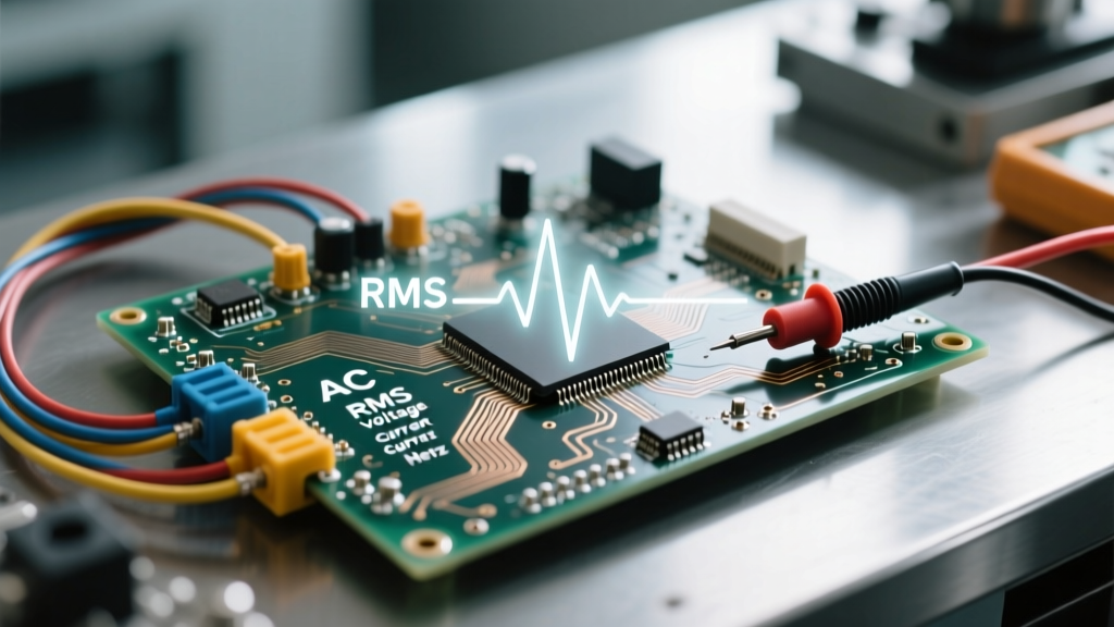
Because non-utility AC sources often have distorted waveforms, you must use a True RMS (Root Mean Square) multimeter. As noted in Fluke's engineering guides, True RMS meters calculate the actual heating value of the AC waveform, giving you an accurate voltage reading regardless of harmonic distortion. If your DIY solar inverter reads 135V on a cheap meter but 120V on a True RMS meter, trust the True RMS meter—the waveform is just heavily distorted.
Summary
Whether it is a 500-ton steam turbine spinning at 3,600 RPM in a coal plant, a wind turbine utilizing power electronics to match grid frequency, or a solid-state inverter on your workbench synthesizing a sine wave from a lithium battery, the sources of alternating current all share the same goal: delivering oscillating electrical energy. Understanding the physics of induction and the nuances of waveform quality will make you a vastly more effective and safe DIY electrical hobbyist.