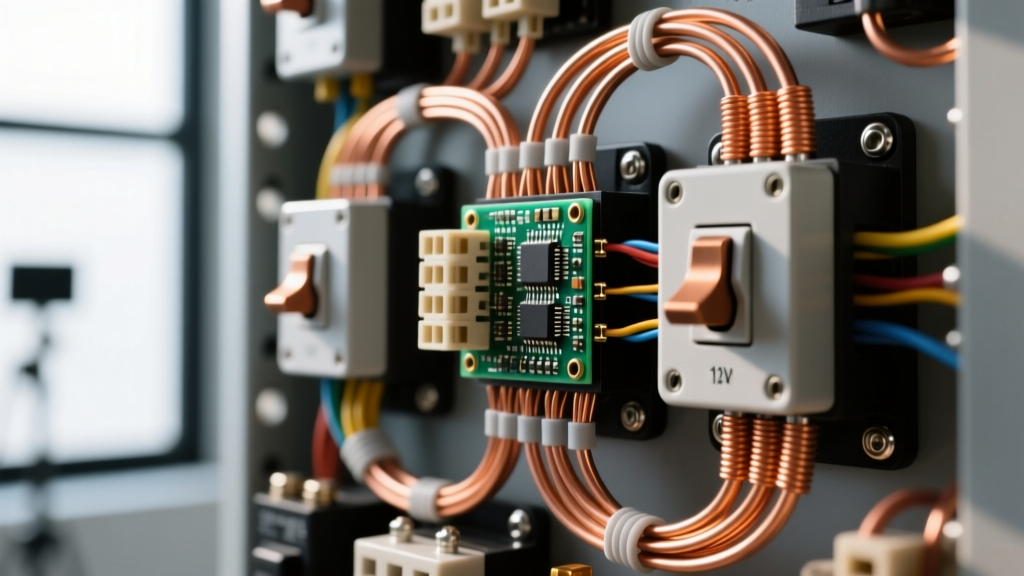
When homeowners ask how to wire a plug switch, they are usually referring to a switched receptacle—a standard duplex outlet where one or both plugs are controlled by a wall switch. This setup is the backbone of living room lighting, allowing you to plug in floor lamps and control them from the door without walking across a dark room.
The direct answer for a standard 15-amp residential circuit is to use 14/2 NM-B (Romex) cable, a 15A single-pole switch, and a 15A tamper-resistant receptacle. The most critical physical step is breaking the brass connecting tab on the hot side of the receptacle so the switch can interrupt the power. Below is the complete, code-compliant procedure to get it right the first time.
Working with 120V AC mains is lethal. Before opening any junction box, you must de-energize the circuit at the main breaker panel. Apply a lockout/tagout device or tape the breaker in the OFF position to prevent accidental re-energizing. Verify the circuit is dead using a non-contact voltage tester (NCVT) and confirm with a multimeter. Never rely solely on a wall switch to isolate power. Local codes (and the OSHA Lockout/Tagout standards) dictate strict safety protocols; if you are unsure, hire a licensed electrician.
Tools, Materials, and Device Ratings
A switched plug circuit requires matching wire gauges to breaker sizes. For standard lighting and lamp loads, a 15-amp circuit using 14 AWG copper is the industry standard. If your breaker is 20A, you must step up to 12 AWG wire and 20A-rated devices.
| Item | Specification / Rating | Recommended Example |
|---|---|---|
| Cable | 14/2 NM-B with Ground (for 15A circuits) | Southwire Romex SIMpull |
| Wall Switch | 15A / 125V Single-Pole, AC Only | Leviton 1451-W |
| Receptacle | 15A / 125V Duplex, Tamper-Resistant (TR) | Leviton T5262-W |
| Voltage Tester | CAT III / CAT IV Non-Contact & Multimeter | Fluke 2AC NCVT & Fluke 117 |
| Wire Strippers | AWG 14-10 solid wire stripping holes | Klein Tools 11055 |
The Most Common Botch: The Unbroken Brass Tab
If you finish wiring your plug switch, turn the breaker back on, and find that the outlet is always hot regardless of the switch position, you forgot to break the brass fin on the receptacle.
Standard duplex receptacles feature a small brass metal tab connecting the top and bottom hot (brass) screws. This tab exists so that a single hot wire can feed both the top and bottom plugs simultaneously. When wiring a switched receptacle, the hot feed comes from the switch. If you leave the tab intact, the internal brass bridge bypasses your switch logic, or if you've wired line and load incorrectly, you may create a dead short that instantly trips the breaker.
The Fix: Use needle-nose pliers to bend the brass tab back and forth until it snaps off cleanly. Leave the silver (neutral) tab completely intact.
Step-by-Step: Wiring the Switch and Receptacle
This procedure assumes you are running a new 14/2 NM-B cable from the switch box to the receptacle box, and that power (Line) is already present at the switch box. All terminations assume solid copper conductors stripped to exactly 3/4 inch.
- De-Energize and Verify: Turn off the 15A breaker. Test the existing wires in the switch box with your NCVT. Follow up by placing your multimeter probes between the Black (hot) and Bare (ground) wires. The reading must be exactly 0.00V.
- Prepare the Switch Box (Line & Load):
- Black (Hot/Line): Connect the Black wire bringing power from the panel to the Brass screw on the single-pole switch.
- Black (Load): Connect the Black wire of the 14/2 cable running to the receptacle to the Black/Dark screw on the switch.
- White (Neutral): Splice the White wire from the panel and the White wire going to the receptacle together using a yellow wire nut. Do not connect neutrals to a standard single-pole switch.
- Bare (Ground): Splice the bare copper from the panel, the bare copper going to the receptacle, and a 6-inch bare copper pigtail. Connect the pigtail to the Green grounding screw on the switch.
- Prepare the Receptacle Box:
- Break the Tab: Snap off the brass tab on the hot side of the receptacle using needle-nose pliers.
- Black (Switched Hot): Connect the Black wire coming from the switch to the Brass screw on the receptacle.
- White (Neutral): Connect the White wire coming from the switch to the Silver screw on the receptacle.
- Bare (Ground): Connect the Bare copper wire to the Green grounding screw on the receptacle.
- Dress the Boxes and Secure: Carefully fold the wires into the back of the junction boxes. Neutrals and grounds go in the back, hots in the front. Mount the devices using the provided machine screws, ensuring the yoke sits flush against the drywall or plaster ring. Install the wall plates.
Verify and Test: Expected Meter Readings
Never assume a circuit is wired correctly just because the breaker didn't trip upon re-energizing. Follow this testing sequence to verify the integrity of your plug switch wiring.
- Restore Power: Turn the 15A breaker back to the ON position.
- Switch OFF Test: Ensure the wall switch is in the OFF position. Insert your multimeter probes into the hot (shorter slot) and neutral (longer slot) of the receptacle. Expected reading: 0V to 2V (ghost voltage is normal on digital meters).
- Switch ON Test: Flip the wall switch to the ON position. Measure the receptacle again. Expected reading: 114V to 126V (the standard acceptable range for a 120V nominal circuit).
- Polarity Check: Use a standard 3-light receptacle tester. You should see two yellow lights indicating "Correct" wiring. If the red light illuminates, you have reversed hot and neutral—turn the breaker off and swap the Black and White wires at the receptacle.
Frequently Asked Questions
Can I use 14 AWG wire for a 20A plug switch circuit?
No. Under NEC Article 240.4(D), 14 AWG copper wire is strictly limited to a maximum 15-amp overcurrent protective device. If your breaker is rated for 20 amps, you must use 12 AWG wire and 20A-rated receptacles (which feature a T-shaped neutral slot). Using 14 AWG on a 20A breaker creates a severe fire hazard, as the wire can melt before the breaker trips during an overload.
Can I wire the switch to break the neutral instead of the hot wire?
Absolutely not. NEC Article 404.2(B) explicitly requires that switches must interrupt the ungrounded (hot) conductor. If you switch the neutral wire, the wall switch will successfully turn the lamp off, but the internal wiring of the plug and the lamp socket will remain energized at 120V. If someone changes a lightbulb or touches a frayed cord while the switch is "off," they will complete the circuit to ground and suffer a lethal shock. Always switch the Black (hot) wire.
Why is my newly wired switched plug tripping the AFCI breaker?
Arc-Fault Circuit Interrupter (AFCI) breakers are highly sensitive to wiring anomalies. If your new plug switch trips the AFCI, the most common culprits are a shared neutral (where the neutral from your switched receptacle is accidentally spliced with a neutral from a different circuit) or a bootleg ground (where the neutral and ground are touching inside the box). AFCIs detect these parallel arcs or neutral-to-ground faults and trip instantly. Isolate the circuit, separate all neutrals, and ensure no bare copper is touching the silver terminal screws.
Do I need a GFCI for a switched plug in a living room?
Generally, no. Ground-Fault Circuit Interrupters (GFCIs) are required by the NEC in areas with water exposure (kitchens, bathrooms, garages, outdoors, and unfinished basements). Standard living rooms and bedrooms require AFCI protection, not GFCI. However, if your switched plug is located within 6 feet of a wet bar sink or an indoor water feature, local AHJ (Authority Having Jurisdiction) interpretations may require GFCI protection. Always consult your local electrical inspector for the final ruling on your specific space.