
Bridging the Gap Between Theory and Execution
Reading an electrical wiring light switch diagram is a fundamental skill for any DIYer or apprentice electrician, but a schematic on paper won't strip a wire or verify a dead circuit. In 2026, with the widespread adoption of smart home ecosystems and stricter National Electrical Code (NEC) requirements, the physical execution of these diagrams demands professional-grade tools and specific materials. A misinterpreted node or a poorly terminated connection can lead to arcing, thermal runaway, or catastrophic failure.
This comprehensive tool and material guide transitions you from theoretical diagram reading to physical installation. We will break down the exact professional-grade equipment required, map specific tools to diagram nodes, and highlight the critical edge cases that separate a safe, code-compliant installation from a hazardous one.
Decoding Diagram Symbols to Physical Actions
Before unboxing your tools, you must understand how the abstract symbols on an electrical wiring light switch diagram translate to physical actions at the workbench. Standard ANSI/IEEE electrical symbols dictate the flow of current:
- Single-Pole Switch (SPST): Represented by a simple break in the line. Physically, this requires interrupting the 'hot' (line/load) conductor while passing the neutral through.
- 3-Way Switch (SPDT): Represented by a break with two alternate paths. This requires identifying the 'common' terminal (usually a dark-colored screw) and the two 'traveler' terminals (brass screws).
- Grounding Node: Indicated by a standard three-line descending triangle. This mandates a physical bond to the metal box (if applicable) and the green grounding screw on the device yoke.
Translating these symbols requires precision tools that respect the physical tolerances of modern 15A and 20A residential devices.
The Professional Toolkit: Exact Models and Specifications
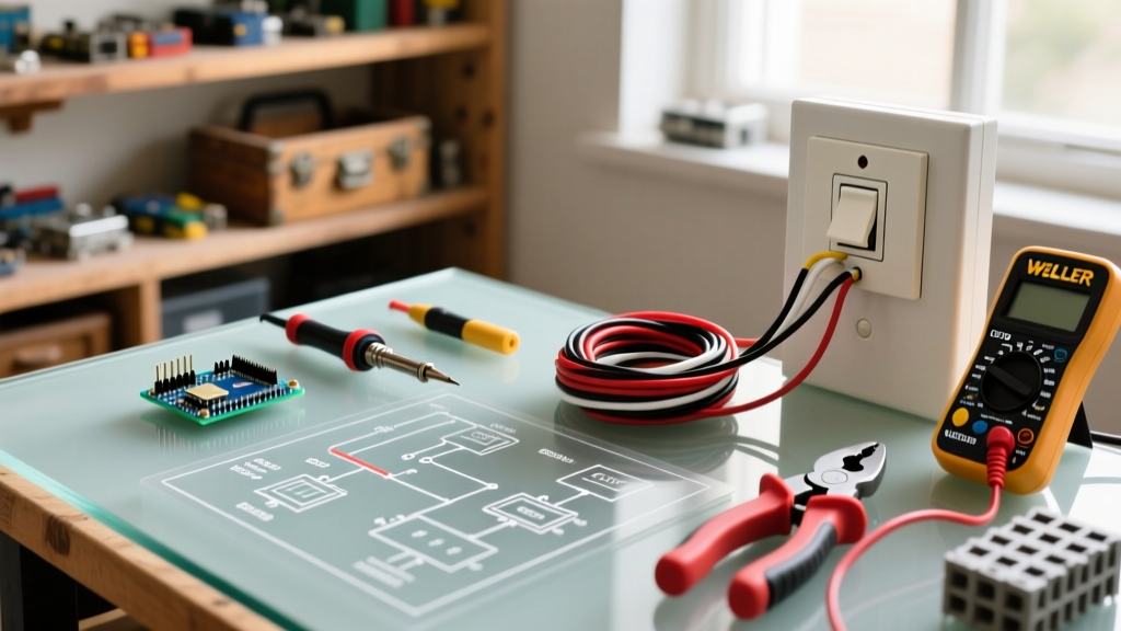
To execute any electrical wiring light switch diagram safely, you must abandon generic hardware store multi-tools. Below is the curated, professional-grade toolkit required for modern switch installations, complete with specific model numbers and current 2026 market pricing.
1. Precision Wire Stripping: Klein Tools 11063W Katapult
Standard combination pliers often nick the copper conductor, creating a localized hot spot that can melt device terminals under continuous load. The Klein Tools 11063W Katapult (approx. $32) features a ratcheting mechanism and precision-machined stripping holes specifically calibrated for 14 AWG and 12 AWG solid copper wire. The compound-action lever strips the jacket cleanly without scoring the metal underneath, which is critical for maintaining the wire's ampacity rating.
2. Voltage Verification: Fluke 1AC-II VoltAlert
Never trust a breaker panel label. The Fluke 1AC-II VoltAlert (approx. $38) is a non-contact voltage tester (NCVT) rated for CAT IV 1000V. Unlike cheaper alternatives that suffer from 'phantom voltage' false positives, the Fluke 1AC-II features a continuous self-test function and a bright red LED indicator paired with an audible beep. It is your primary defense against shock hazards when verifying the 'Line' and 'Load' nodes on your diagram.
3. Torque and Terminal Driving: Wiha SoftFinish Insulated Screwdrivers
Modern switches, particularly smart switches and GFCI/AFCI combo devices, require specific torque values to prevent terminal loosening over time due to thermal expansion. The Wiha SoftFinish Insulated Screwdriver Set (approx. $45 for a multi-bit set) is VDE-certified to 1000V. The ergonomic handle allows for precise torque application on brass terminal screws without the risk of the driver slipping and shorting against the metal wall box.
4. Splicing and Pigtailing: Wago 221-413 Lever Nuts
When your electrical wiring light switch diagram calls for a neutral pigtail to feed a smart switch or smart dimmer, traditional twist-on wire nuts can fail if the installer lacks the wrist strength to twist three 14 AWG wires together. Wago 221-413 Lever Nuts (approx. $0.65 each) are the industry standard. They accept 24-12 AWG solid or stranded wire, feature a transparent housing to visually verify the 11mm strip length, and maintain a constant spring-pressure clamp that resists vibration and thermal cycling.
Material Matrix: Selecting the Right Components
Matching the right materials to your diagram is just as critical as the tools. The table below outlines the standard materials required for a typical 15A residential lighting circuit in 2026.
| Component | Recommended Brand/Model | Specification | Use Case in Diagram | Approx. Cost |
|---|---|---|---|---|
| Non-Metallic Cable | Southwire Romex SIMpull | 14/2 AWG NM-B (90°C) | Main feed (Line, Neutral, Ground) for 15A circuits | $0.55 / ft |
| Single-Pole Switch | Leviton Decora 5601-2W | 15A, 120V, Auto-Ground | Standard SPST lighting control | $4.25 |
| Smart Switch Base | Lutron Caseta PD-5S-DV | 15A, Requires Neutral | Automated control (Requires neutral node at box) | $65.00 |
| Wire Connectors | Wago 221-413 (3-Port) | 41A, 600V, Lever-Action | Splicing neutrals, pigtailing grounds | $0.65 / ea |
| Electrical Box | Carlon B618R-UPC | 1-Gang, 18 cu. in. PVC | Housing the switch and wire splices | $1.15 |
Mapping the Diagram: Execution and Code Compliance
When you look at your electrical wiring light switch diagram, you will identify four distinct conductors. Here is how to handle each using the tools and materials listed above:
The Grounding Conductor (Bare/Green)
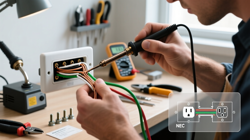
According to the National Fire Protection Association (NFPA 70), all grounds must be bonded. Use your Klein strippers to remove 1 inch of insulation (if using green THHN) or leave the bare copper as-is. Secure the ground to the metal box using a green 10-32 grounding screw, then pigtail it to the switch's green ground screw using a Wago 221 lever nut.
The Neutral Conductor (White)
Historically, single-pole switch boxes did not require a neutral. However, modern smart switches and the latest NEC cycles mandate a neutral at the switch location. If your diagram shows a smart switch, you must cap the incoming neutral and the outgoing neutral to the fixture together with a Wago connector, and run a separate pigtail to the smart switch's white wire. Never connect a neutral wire to the brass or black screws of a standard switch.
The Line and Load Conductors (Black/Red)
The Line brings power from the panel; the Load carries power to the fixture. On a standard single-pole Leviton Decora switch, these connect to the brass terminals. Strip exactly 3/4 inch of insulation. Loop the wire clockwise around the terminal screw so that tightening the screw pulls the loop closed, rather than pushing it out. Torque until the screw is snug, but avoid over-torquing which can strip the brass threads.
Critical Failure Modes and Edge Cases
Even with a perfect electrical wiring light switch diagram, physical installation errors cause the majority of residential electrical fires. Avoid these specific failure modes:
NEC Code Alert: Under NEC Article 110.12, mechanical execution of work must be 'neat and workmanlike.' Over-stripping wires, leaving exposed copper outside the terminal, or cramming wires into an undersized box violates this code and creates severe arc-flash hazards.
- Backstabbing Failures: Many budget switches feature push-in 'backstab' terminals on the rear. While technically legal, these rely on a tiny internal spring clip that can lose tension over years of thermal cycling. Always use the side screw terminals or, if the device supports it, the screw-clamp plates. The U.S. Consumer Product Safety Commission (CPSC) frequently notes poor terminal connections as a leading cause of residential electrical fires.
- Box Fill Violations: Every wire, clamp, and device adds to the 'box fill' calculation. A standard single-pole switch counts as two wire volumes. If you are using 14 AWG wire (2.0 cubic inches per volume), a switch with multiple pigtails can easily exceed the capacity of a standard 12-cubic-inch shallow box. Always use deep 18-cubic-inch or 22-cubic-inch boxes for switch locations with multiple cables.
- Phantom Travelers in 3-Way Diagrams: When wiring a 3-way circuit, a common mistake is misidentifying the 'common' terminal. The common terminal is almost always a dark-colored (black or dark brass) screw, while the travelers are standard brass. Connecting the line feed to a traveler terminal will result in a circuit that only works in one of the two switch positions.
Safety First: Verification Before Energizing
Before restoring power at the breaker panel, conduct a visual and physical inspection. Tug gently on every wire connected to a Wago lever nut and every screw terminal. Ensure no bare ground wires are touching the brass line/load terminals. Once the breaker is restored, use your Fluke VoltAlert to verify that the metal faceplate screws and the switch yoke are completely de-energized, confirming a proper ground bond.
For further reading on workplace and residential electrical safety protocols, consult the Occupational Safety and Health Administration (OSHA) electrical safety guidelines, which provide extensive documentation on lockout/tagout (LOTO) procedures that every DIYer should emulate when working on residential panels.
Final Thoughts
An electrical wiring light switch diagram is your roadmap, but your tools and materials are the vehicle. By investing in precision strippers, reliable voltage testers, and modern lever-nut connectors, you ensure that the physical installation perfectly mirrors the theoretical safety of the schematic. In 2026, there is no excuse for sloppy terminations or outdated materials; precision is the standard for safety.