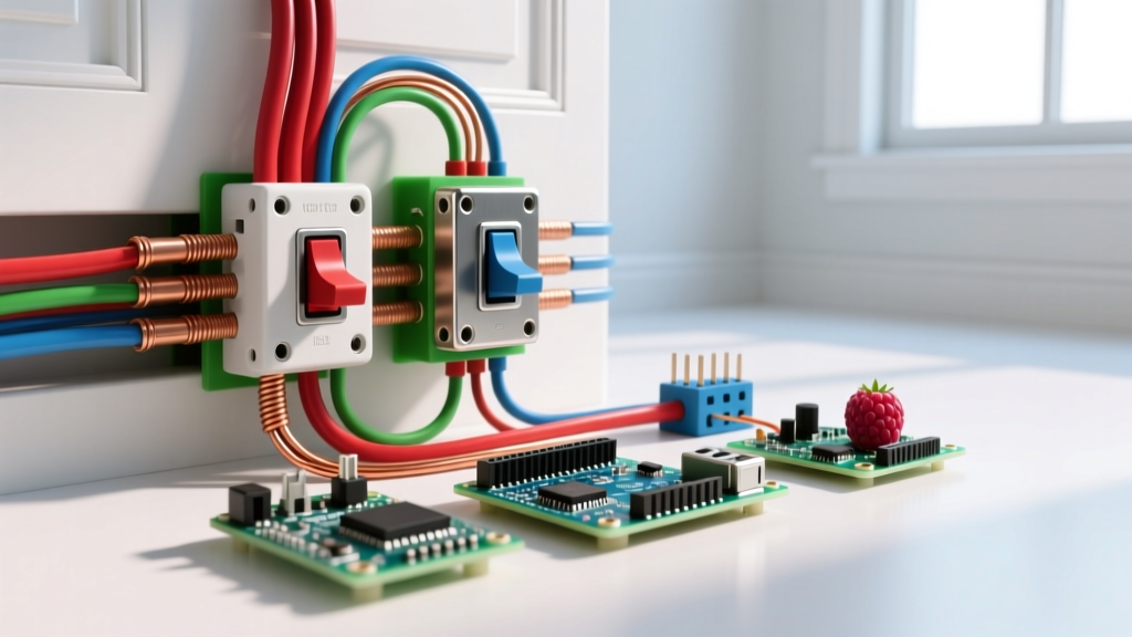
To identify an existing electromechanical switch—whether it is a heavy-duty toggle, a control relay, or a power contactor—locate the manufacturer nameplate and record three critical values: the coil voltage (e.g., 24VAC, 120VAC, or 12VDC), the contact current rating (e.g., 30A), and the utilization category (e.g., AC-3 for motors). If the nameplate is illegible, you must trace the control wiring to determine the coil voltage and measure the load current to size the contacts.
Reading the Nameplate: Decoding Coil and Contact Ratings
The nameplate is your single source of truth, but it is packed with dense IEC and NEMA codes. The most common mistake DIYers make is looking only at the maximum amperage number and ignoring the load type. A switch rated for 30A on a resistive heater might weld its contacts shut if used to start a 30A compressor motor due to inrush current.
Here is how to read the rating table on a standard industrial contactor or relay:
| Nameplate Parameter | What It Means | Typical Values |
|---|---|---|
| Coil Voltage (Us) | The voltage required to energize the electromagnet and pull the contacts closed. | 24VAC, 120VAC, 240VAC, 12VDC, 24VDC |
| Thermal Current (Ith) | Maximum continuous current the contacts can carry in open air without overheating. | 20A, 32A, 40A, 63A |
| Utilization Category | The specific load type the switch is certified to break safely. This is the column that governs your load. | AC-1, AC-3, AC-4, DC-13 |
| Breaking Capacity | The maximum fault or inrush current the contacts can interrupt without welding together. | e.g., 250A at 400V for AC-3 |
Which rating column governs this load? You must match the utilization category to your application. According to IEC 60947-4-1 standards, an AC-1 rating applies to non-inductive or slightly inductive loads like heater banks. An AC-3 rating applies to squirrel-cage motors (starting and switching off during run). If your nameplate says "30A AC-1 / 10A AC-3", and you are controlling a motor, your switch is only good for 10A. Sizing it for 30A will result in melted contacts.
Coil vs. Contact Wiring: The Control and Power Divide
Electromechanical relays and contactors isolate the low-power control circuit from the high-power load circuit. Understanding this divide is critical when tracing wires to figure out what switch you have.
- The Coil (Control Side): Typically labeled A1 and A2. This is the electromagnet. When voltage is applied across A1 and A2, it generates a magnetic field that pulls the mechanical armature. Coil wires are usually smaller gauge (18-14 AWG) and originate from a thermostat, PLC, or microcontroller relay board.
- The Contacts (Power Side): Typically labeled with Line/Load pairs like L1/T1, L2/T2, and L3/T3 for 3-phase, or simply numbered 1/2, 3/4 for single-phase and DC. Auxiliary contacts used for feedback logic are usually labeled NO (Normally Open, e.g., 13/14) or NC (Normally Closed, e.g., 21/22). Power wires are sized to the load (e.g., 10 AWG for 30A).
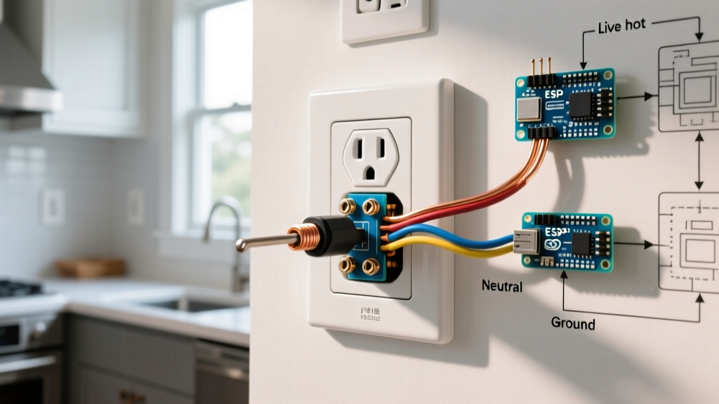
If you identify a switch with a DC coil (e.g., 12VDC or 24VDC) driven by a solid-state device like an Arduino, ESP32, or a transistor (TIP120), you must wire a flyback diode (like a 1N4007) in reverse parallel across the A1 and A2 terminals. When the DC coil de-energizes, the collapsing magnetic field generates a massive reverse voltage spike that will instantly destroy your driving transistor or microcontroller GPIO. AC coils do not require this, as the alternating current naturally crosses zero and extinguishes the arc.
Live and Dead Testing: Verifying Switch Health
Once you know what switch you have, you need to know if it is actually working. Electromechanical switches fail in two primary ways: an open coil (fails to pull in) or pitted/welded contacts (fails to pass power or fails to drop out).
Dead Testing (Power Off & Locked Out)
Set your multimeter to resistance (Ohms) mode. Verify the circuit is dead before proceeding.
- Test the Coil: Place probes on A1 and A2. A healthy AC coil typically reads between 10Ω (for 24VAC) and 300Ω (for 240VAC). A reading of "OL" (infinite) means the internal copper winding is broken; the coil is dead. A reading of 0.0Ω means it is shorted.
- Test the Contacts: Place probes across L1 and T1. With the switch de-energized, normally open (NO) power contacts should read "OL". If you read < 0.5Ω, the contacts are welded shut from arcing and the switch must be replaced.
Live Testing (Energized)
If the dead tests pass but the load still isn't running, perform a live voltage test. Set your meter to AC or DC Volts, matching the coil rating.
- Verify Coil Voltage: Measure directly across A1 and A2 while the control signal is active. If you read the nominal voltage (e.g., 24VAC ± 10%) but the contactor is humming loudly and not pulling in, the mechanical armature is jammed with debris or the shading coil (a small copper ring on the AC magnet core) is cracked.
- Measure Contact Voltage Drop: With the switch pulled in and the load running, measure the voltage across the closed contacts (from L1 to T1). A healthy contact will drop less than 50mV (0.05V). If you read several volts dropping across the closed contact, the silver-alloy contact face is severely pitted and generating dangerous heat.
When to Repair vs. Replace
The decision to repair or replace depends entirely on the physical size and NEMA/IEC frame of the switch.
- Replace: Control relays, PCB-mounted relays, and definite-purpose contactors under 40A (like those in HVAC units) are sealed or riveted units. If contacts are pitted or the coil is open, throw it in the bin. Attempting to file down pitted contacts removes the silver-cadmium or silver-nickel plating, exposing the base copper, which will oxidize and fail within weeks.
- Repair: Large industrial NEMA size 2 through 5 contactors (typically 45A to 270A+) feature bolted, replaceable contact tips and modular arc chutes. If the coil tests open, you can unbolt the A1/A2 terminals and swap just the coil assembly for $40-$80 instead of replacing the $400+ contactor body.
Load-Type Decision Path: Picking the Exact Replacement
If your switch is dead and beyond repair, use this decision tree to select the correct replacement. Do not just match the amperage; match the load physics.
| Load Type | Characteristics | Required Rating | Concrete Part Selection |
|---|---|---|---|
| Resistive | Heaters, incandescent lighting. No inrush current. | AC-1 | Standard DP Contactor (e.g., 30A AC-1) |
| Inductive (Motor) | Compressors, pumps, fans. 6x inrush current on startup. | AC-3 / AC-4 | IEC Motor Contactor (e.g., 9A AC-3) |
| DC Coil Control | Driven by PLCs, smart thermostats, or microcontrollers. | DC Coil, AC Contacts | Contactor with DC coil variant |
The Decision Path:
- Is the load a 3-phase industrial motor? If yes, you must use an IEC-style motor contactor rated for AC-3. Pick the Schneider Electric TeSys LC1D series matched to your motor's FLA (Full Load Amps).
- Is the load a single-phase 240V HVAC compressor or resistive heater? If yes, you need a Definite Purpose (DP) contactor. These are the workhorses of residential and light commercial refrigeration.
- Is your control circuit 24VAC (standard thermostat voltage) and your load under 30A? If yes, you have arrived at the most common replacement scenario in North American HVAC and DIY automation.
For a direct, drop-in replacement for a failed 30-Amp, 2-pole, 24VAC coil contactor in an HVAC condenser, heat pump, or heavy-duty resistive load, buy the Eaton C25DND230A. It features a highly reliable 24VAC coil, dual 30A contacts rated for both resistive and motor loads, and standard 1/4" quick-connect spade terminals for the coil and box lugs for the power wires. It typically retails for $25 to $35, requires no complex IEC derating math for single-phase 120/240V applications, and will reliably switch millions of cycles.