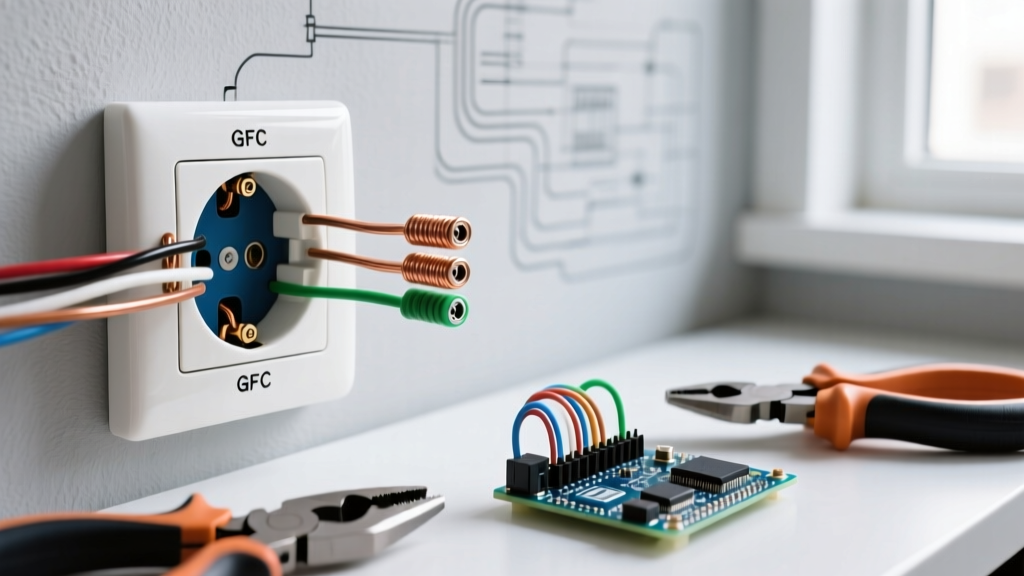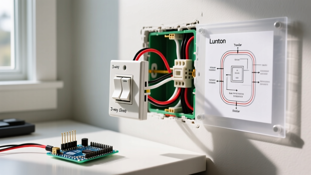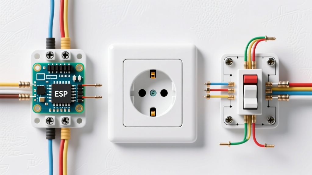

Understanding the Anatomy of a Receptacle
Before you strip a single wire or flip a breaker, any serious DIYer must understand the physical hardware they are working with. An electrical receptacle is not just a plastic block with holes; it is a precisely engineered mechanical and electrical interface. In 2026, with stricter energy codes and updated National Electrical Code (NEC) mandates, using the right components and understanding how they interact is critical for passing inspection and preventing residential fires.
Whether you are upgrading a 1970s ungrounded two-prong outlet to a modern Tamper-Resistant (TR) duplex receptacle or wiring a split-circuit kitchen counter, knowing your electrical outlet parts is the foundation of safe wiring.
⚠️ Safety First: Always verify power is off at the breaker panel using a non-contact voltage tester (like the Klein NCVT-3) before removing any faceplate. Never rely solely on a wall switch to isolate power.The Core Electrical Outlet Parts Explained
Let us break down the physical components of a standard 15-amp, 125-volt duplex receptacle (such as the industry-standard Leviton T5320-W).
| Part Name | Function | Material / Specification |
|---|---|---|
| Faceplate | Covers the yoke and drywall cutout, preventing accidental contact with live terminals. | Polycarbonate or Nylon (unbreakable) |
| Yoke (Mounting Strap) | The metal framework that secures the device to the electrical box via the top and bottom mounting screws. | Zinc-plated steel or brass |
| Receptacle Body | Houses the internal brass contacts and provides structural insulation. | Thermoplastic (PVC or Nylon) |
| Terminal Screws | Secures the hot and neutral wires to the internal contacts. | Brass (Hot) and Silver (Neutral) |
| Grounding Screw | Provides a low-impedance path to earth ground for fault currents. | Green-coated brass or steel |
| Break-Off Fins | Small metal tabs connecting the top and bottom terminals, designed to be snapped off for split-wiring. | Brass (Hot side only) |
| Shutter Mechanism | Internal spring-loaded gates that prevent foreign objects from being inserted into the slots. | Internal POM plastic (TR models) |
The Terminal Debate: Back-Stab vs. Screw vs. Back-Wire
When examining the back and sides of your electrical outlet parts, you will notice different methods for terminating wires. Choosing the right method is the difference between a lifelong connection and a melted junction box.
1. Push-In (Back-Stab) Terminals
These are the small holes on the back of the device that accept 14 AWG solid wire. They use internal spring-loaded brass clamps to grip the wire. Expert Advice: Never use these. While legal under older code cycles, they are notorious for high-resistance connections, arcing, and eventual thermal failure. The spring tension weakens over time, especially under heavy thermal cycling from space heaters or window AC units.
2. Side-Wiring (Screw Terminals)
The traditional method. You strip the wire, form a 'J-hook' with needle-nose pliers, loop it clockwise around the brass or silver screw, and tighten. This provides a reliable mechanical and electrical bond.
3. Back-Wiring (Screw-Clamp)
Found on Commercial and Hospital Grade receptacles (like the Eaton TRCR15W). You insert the straight-stripped wire into a hole on the back, and tightening the side screw pulls an internal metal plate down, clamping the wire securely. This is the fastest, most secure method and accepts both 12 AWG and 14 AWG wire.
Step-by-Step Beginner Installation Tutorial
Now that you know the parts, here is how to wire a standard 15A TR duplex receptacle safely and to modern code standards.
Tools Required
- Klein Tools 11055 Wire Stripper
- Phillips #2 Screwdriver
- Calibrated Torque Screwdriver (e.g., CDI 401SM)
- Non-Contact Voltage Tester
Step 1: Precision Stripping
Strip exactly 3/4-inch of insulation from your 14 AWG or 12 AWG solid copper wire. Most premium receptacles have a physical 'strip gauge' molded into the back of the plastic body. If your stripped wire is too long, exposed copper will sit outside the terminal, creating a shock hazard. If it is too short, the insulation will bind under the screw plate, causing an open circuit.
Step 2: Forming the Loop (Side-Wiring)
If using side terminals, use the bending hole in your wire strippers to create a perfect 180-degree hook. Critical Rule: Always loop the wire clockwise around the terminal screw. As you tighten the screw (which turns clockwise), the screw head will pull the loop tighter. A counter-clockwise loop will be pushed out from under the screw head as you tighten it.
Step 3: Torquing to Code
Modern electrical standards have eliminated the 'tighten until it feels right' approach. According to OSHA Electrical Safety Standards and NEC Article 110.14(D), connections must be tightened to the manufacturer's specified torque. For most standard 15A receptacles, this is between 12 and 14 inch-pounds (0.75 Nm). Using a calibrated torque screwdriver ensures the wire is secure without stripping the brass screw head or crushing the copper wire.
Code Note: The CPSC mandates that all new residential receptacles must be Tamper-Resistant (TR). The internal shutters require equal pressure on both slots to open, preventing children from inserting objects. Learn more via the CPSC Tamper-Resistant Receptacle Guidelines.
Mastering Break-Off Fins and Split Receptacles
In kitchens and living rooms, you often encounter 'split receptacles'—where the top half is controlled by a wall switch (for lamps) and the bottom half is always hot. To achieve this, you must utilize the break-off fins located on the hot (brass) side of the yoke.
Using a pair of lineman's pliers, grip the small brass tab between the top and bottom brass screws and snap it off. This electrically isolates the top and bottom receptacles. Warning: Never break the silver (neutral) fin unless you are working on a specific Multi-Wire Branch Circuit (MWBC) and local code explicitly permits it. In 2026, best practice dictates pigtailing neutrals in the back of the box rather than relying on the device's neutral fin to carry return current for two separate circuits.
Troubleshooting Common Failure Modes
When replacing old electrical outlet parts, look for these specific failure signatures to diagnose underlying circuit issues.
| Symptom | Failed Part / Root Cause | Solution |
|---|---|---|
| Plugs fall out easily | Wiped-out internal brass contact springs inside the receptacle body. | Replace the receptacle immediately; the internal tension is gone, causing arcing. |
| Faceplate is warm to touch | Loose back-stab terminal or under-torqued side screw causing high resistance. | Cut off damaged wire ends, strip fresh copper, and use side-screw or back-wire clamps. |
| Receptacle sits crooked | Bent yoke or missing box leveling screws. | Use a metal box extender or specialized leveling shims (like the Caddy Snap) behind the yoke. |
| Top half dead, bottom works | Unintentionally broken brass break-off fin during previous installation. | Check wiring; if a switch loop is missing, pigtail the hot wire to both terminals. |
Sourcing the Right Components: 2026 Buyer's Guide
Not all electrical outlet parts are created equal. When shopping at your local supplier, you will generally encounter three grades of receptacles:
- Residential Grade ($1.50 - $3.00): Standard TR duplex receptacles. Fine for bedrooms and low-draw areas, but the internal contacts are thinner and the yoke is lighter.
- Commercial / ProGrade ($4.00 - $8.00): Features heavy-gauge steel yokes, thicker brass contacts, and back-wire clamp plates. Highly recommended for kitchens, garages, and high-use areas.
- Hospital Grade ($12.00 - $18.00): Identified by a green dot on the face. Built with extreme impact resistance and ultra-tight grip tension. Usually overkill for residential, but excellent for workshops with heavy vibration tools.
By understanding the exact function of every yoke, terminal, and break-off fin, you transition from simply 'plugging things in' to executing professional-grade electrical installations that will safely power your home for decades.