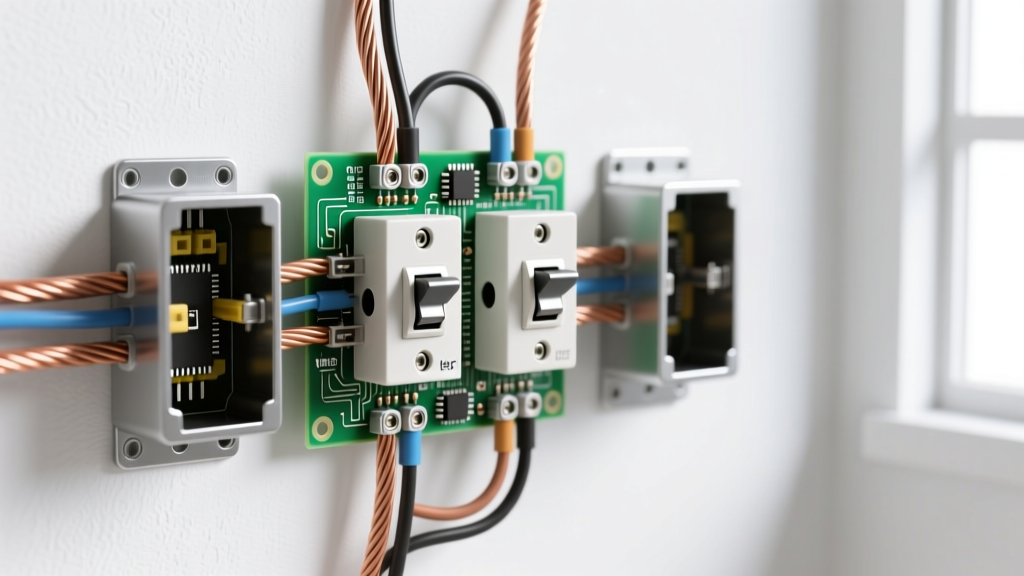

The Hidden Dangers of Non-Compliant 3-Way Circuits
When homeowners and novice DIYers attempt a basic 3 way switch wiring project, the primary focus is usually on getting the light to turn on from two locations. However, from a professional electrical standpoint, making the circuit function is only half the battle. The true measure of a successful installation lies in strict adherence to the National Electrical Code (NEC). Non-compliant 3-way switch wiring introduces severe shock hazards, creates thermal overload risks inside junction boxes, and can lead to catastrophic arc faults.
At ElectricalFlux, we prioritize safety and code compliance above all else. This comprehensive guide deconstructs the NEC requirements for 3-way switch loops, focusing on conductor re-identification, box fill mathematics, proper grounding topology, and the modern mandates for neutral conductors at switch locations.
NEC 404.2(A): The Mandatory Switch Loop Neutral
Historically, basic 3 way switch wiring diagrams only required a hot, a switched leg, and two travelers. The neutral was spliced directly in the ceiling fixture box or the first switch box, bypassing the second switch location entirely. This legacy method is now a direct violation of modern electrical codes.
NEC 404.2(C) states that for switch loops, a grounded circuit conductor (neutral) must be provided at the switch location to accommodate smart switches, timers, and occupancy sensors that require a continuous 120V reference.
Even if you are installing standard, dumb toggle switches today, you must route a 14/3 or 12/3 NM-B cable to both switch locations to ensure the neutral is present. Failing to do so forces future electricians to rip open finished drywall to upgrade the circuit for smart home integrations, and it often tempts DIYers to illegally use the equipment grounding conductor as a neutral return path—a lethal practice that bypasses GFCI protection and electrifies appliance chassis.
Deconstructing the Traveler Configuration & Conductor Re-Identification
The hallmark of a 3-way circuit is the pair of traveler wires that shuttle the hot potential between the two switch terminals. In standard residential wiring, these travelers are typically the red and black conductors of a 3-wire Romex cable. However, physical routing constraints often require electricians to use the white conductor as a traveler or a continuous hot leg.
The 'White Traveler' Code Violation (NEC 200.7)
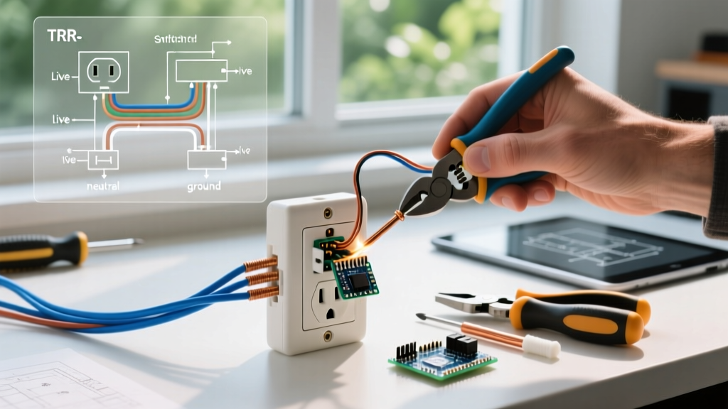
Using a white wire as an ungrounded (hot) conductor is permissible under specific conditions, but leaving it uninsulated and unmarked is a massive safety violation. Future technicians troubleshooting the circuit will assume the white wire is a neutral, leading to severe arc flashes or electrocution when they disconnect it under load.
- NEC 200.7(C)(1) Mandate: If a white or gray wire is used as an ungrounded conductor (hot or traveler), it must be permanently re-identified at every termination point.
- Acceptable Methods: Wrap the wire with black or red electrical tape, or use heat-shrink tubing. Painting the wire is technically allowed by the code but heavily discouraged in practice due to poor adhesion and flaking over time.
- Pro-Tip: Always re-identify the white wire at both the switch box and the fixture/junction box. A common failure mode is taping the wire at the switch but leaving it bare at the ceiling canopy.
Box Fill Calculations: Preventing Thermal Overload
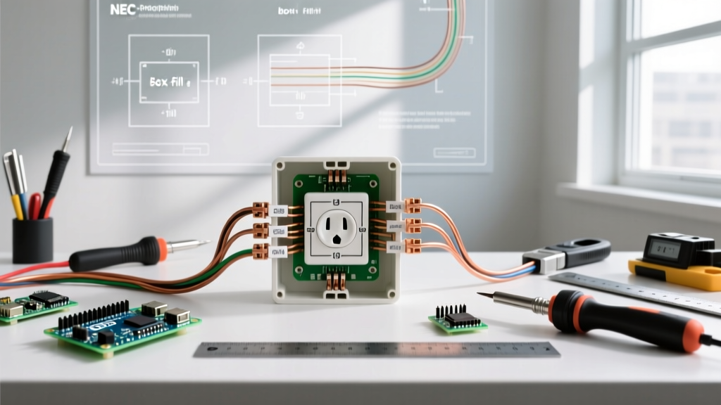
One of the most frequently cited violations during municipal rough-in inspections is box overcrowding. 3-way switch boxes inherently contain more conductors than standard single-pole switch boxes. Cramming six or seven 12 AWG wires into a standard 14-cubic-inch single-gang box damages wire insulation, creates excessive heat buildup, and makes it physically impossible to seat the switch properly without pinching the equipment ground.
According to EC&M National Electrical Code Resources, box fill is calculated based on the largest conductor in the box. Below is the standard deduction table for 3-way switch enclosures.
| Box Component | 14 AWG Volume (cu in) | 12 AWG Volume (cu in) |
|---|---|---|
| Each Hot, Neutral, or Traveler | 2.0 | 2.25 |
| Switch Device (Counts as 2 wires) | 4.0 | 4.5 |
| All Equipment Grounds (Combined) | 2.0 | 2.25 |
| Internal Cable Clamps | 2.0 | 2.25 |
Real-World Calculation Example: Imagine a first-position 3-way switch box containing a 14/2 line-in, a 14/3 line-out to the second switch, and a 14/2 feed to a downstream receptacle.
• Line-in (Hot, Neutral): 2 wires x 2.0 = 4.0 cu in.
• Line-out (Hot, Neutral, Traveler 1, Traveler 2): 4 wires x 2.0 = 8.0 cu in.
• Downstream feed (Hot, Neutral): 2 wires x 2.0 = 4.0 cu in.
• Switch Device: 4.0 cu in.
• Grounds (1 allowance): 2.0 cu in.
• Clamps (1 allowance): 2.0 cu in.
Total Required Volume: 24.0 cubic inches. A standard single-gang old-work box (typically 14-18 cu in) will fail this inspection. You must use a deep 2-gang box or a specialized 24+ cu in. masonry/pan box to remain code-compliant.
Grounding Topology and Terminal Torque Specifications
Safety in basic 3 way switch wiring extends beyond the current-carrying conductors. The equipment grounding conductor (EGC) provides the critical low-impedance path necessary to trip the breaker during a fault.
Pigtailing vs. Daisy-Chaining Grounds
Never rely on the metal yoke of the switch or the mounting screws to bond the ground path between devices in a multi-gang box. Furthermore, do not daisy-chain grounds by looping the bare wire through one switch terminal and continuing to the next. NEC 250.148 requires that equipment grounding conductors be spliced together using a wire nut, crimp sleeve, or push-in connector, with a dedicated pigtail run to each switch's green grounding screw. This ensures that removing one switch for replacement does not sever the ground path for downstream devices.
The Overlooked Torque Requirement (NEC 110.14(D))
Since the 2017 NEC cycle, and reinforced in the 2023/2026 updates, terminations must be tightened to the manufacturer's specified torque. While often ignored in residential retrofits, failing to use a calibrated inch-pound torque screwdriver on the brass traveler screws and the common terminal can result in high-resistance connections. Over time, thermal expansion and contraction will loosen under-torqued screws, leading to arcing, melted switch housings, and potential electrical fires. Most commercial-grade 3-way switches (like the Leviton Decora 5603 or Lutron Claro) require between 12 to 14 inch-pounds of torque.
AFCI and GFCI Protection in 3-Way Branch Circuits
Modern code compliance requires strict adherence to ground-fault and arc-fault protection depending on the room's classification. When wiring a 3-way circuit in a kitchen, bathroom, garage, or unfinished basement, the circuit must be protected by a GFCI. In living areas, bedrooms, and hallways, AFCI protection is mandated by NEC 210.12.
The challenge with basic 3 way switch wiring is that standard GFCI/AFCI receptacles cannot easily protect a multi-location switch loop if the load is situated between the two switches. The most code-compliant and reliable solution is to install a GFCI or AFCI circuit breaker in the main service panel, thereby protecting the entire branch circuit, including all travelers and switch legs, without the risk of nuisance tripping caused by miswired load-side terminals on downstream devices.
Troubleshooting Existing Code Violations
When upgrading or repairing older homes, electricians frequently encounter dangerous legacy wiring. If you are opening up an existing 3-way setup, look for these critical failure modes:
- The 'California' or 'Coast' 3-Way: An obsolete, highly dangerous wiring method where both the hot and the neutral are switched simultaneously on the travelers. This leaves the light socket energized at 120V even when the light is off, posing a lethal shock hazard to anyone changing a bulb. This must be entirely rewired.
- Phantom Voltage on Travelers: When running 14/3 NM-B cable over distances exceeding 50 feet, parallel conductors can induce phantom voltages (often 30V-60V) on the disconnected traveler due to capacitive coupling. While not a code violation, it can cause LED fixtures to ghost or flicker. Installing a 10k-ohm bleeder resistor at the fixture resolves this without violating NEC standards.
- Backstabbed Terminations: Older switches often feature push-in backwire holes. These spring-loaded connections are notorious for failing under the continuous load of modern LED drivers. Always use the side-binding plate screws or the internal screw-clamp backwiring holes for a secure, code-compliant mechanical bond.
Final Safety Verification
Before energizing a newly wired 3-way circuit, perform a dead-front continuity test with a digital multimeter to verify the traveler paths and ensure no short circuits exist between the hot and the ground. For authoritative guidance on ongoing code updates, always consult the National Fire Protection Association (NFPA) and your local Authority Having Jurisdiction (AHJ). Proper basic 3 way switch wiring is not just about convenience; it is about ensuring the long-term safety and integrity of your home's electrical infrastructure.