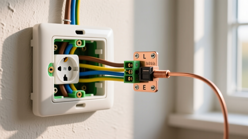
To wire a 2 gang light switch controlling two separate lights from a single location, you will typically use 14 AWG copper wire on a 15-amp breaker (or 12 AWG on a 20-amp breaker). The incoming hot (black) wire connects to a brass screw on both switches via a pigtail, the two outgoing load wires (black) connect to the remaining brass screws, and all bare copper grounds bundle together and pigtail to the green ground screws. Standard single-pole switches do not have designated 'line' or 'load' screws; either brass screw can accept the incoming hot or the outgoing load.
Tools, Materials, and Device Ratings for a 2-Gang Box
Before opening your electrical panel or cutting any drywall, gather the correct materials. Using undersized wire or unlisted devices is a direct violation of NEC Article 110.2 and a primary cause of residential electrical fires. For a standard residential lighting circuit, your switches must be rated for at least 15A and 120V AC. Models like the Leviton 5622 (standard toggle) or Lutron Diva DV-15PH (rocker) are industry benchmarks.
| Material / Tool | Specification | Purpose & Notes |
|---|---|---|
| NM-B Cable (Line) | 14/2 or 12/2 with Ground | Incoming power from the breaker panel. Use 14 AWG for 15A circuits, 12 AWG for 20A. |
| NM-B Cable (Load) | 14/2 or 12/2 with Ground (x2) | Outgoing power to the two separate light fixtures. |
| Single-Pole Switches | 15A, 120V AC, UL-Listed | Two units required. Ensure they have a green ground screw and two brass terminal screws. |
| Wire Nuts | Yellow (14 AWG) / Red (12 AWG) | For bundling 3 or more conductors. Use the manufacturer's strip gauge. |
| Wire Strippers | Klein 11055 or equivalent | Must have dedicated 14 and 12 AWG stripping holes to avoid nicking the copper. |
| Multimeter & NCV Tester | CAT III 600V rated minimum | Mandatory for verifying the circuit is de-energized before touching conductors. |
Critical Safety Protocol: De-Energize and Verify
- Locate and trip the breaker: Identify the correct 15A or 20A breaker in your main panel and switch it to the OFF position.
- Non-Contact Voltage (NCV) Test: Remove the switch faceplate. Hold your NCV tester near the switch terminals. If it beeps or flashes red, the wrong breaker was tripped. Stop and find the correct breaker.
- Multimeter Verification (The 'Live-Dead-Live' Test): Set your multimeter to AC Voltage (V~). First, test the meter on a known live outlet (Live). Next, test between the black wire and the bare ground wire in the 2-gang box (Dead - expect 0.0V). Finally, test the known live outlet again to ensure the meter didn't blow its internal fuse mid-test (Live).
Step-by-Step: How to Wire a 2 Gang Light Switch
This procedure assumes the most common US wiring topology: one 14/2 incoming line cable and two 14/2 outgoing load cables entering the 2-gang box. According to Electrical Technology standards, proper conductor routing and termination torque are critical for preventing arc faults.
- Prepare the Conductors: Strip exactly 3/4-inch of insulation from all black, white, and bare copper wires. Use the built-in gauge on the back of your Leviton or Lutron switch to verify the strip length. If the bare copper is longer than 3/4-inch past the insulation, trim it to prevent exposed ground wires from accidentally touching the brass terminals.
- Bundle the Grounds (Bare Copper): Gather the three bare copper ground wires (one from the line, two from the loads). Add a 6-inch piece of bare 14 AWG copper as a pigtail. Twist them together clockwise with lineman's pliers and secure with a yellow wire nut. Wrap the free end of the pigtail clockwise around the green ground screw on Switch 1 and tighten. Repeat this exact process for Switch 2. (Note: If using a metal 2-gang box, you must also run a ground pigtail to the box's internal grounding clip or 10-32 ground screw).
- Pass Through the Neutrals (White): Gather the three white neutral wires. Do not connect them to the switches. Standard single-pole switches only break the hot leg. Add a pigtail only if you are installing a smart switch later that requires a neutral; otherwise, simply twist the three white wires together, cap them with a red wire nut, and push them neatly into the back of the 2-gang box.
- Create the Hot Pigtail (Black Line): Take the incoming black line wire and two 6-inch pieces of black 14 AWG wire. Twist all three together and cap with a yellow wire nut. This splits the incoming power to feed both switches simultaneously.
- Terminate the Line Hots: Take the free end of the first hot pigtail and loop it clockwise around one of the brass terminal screws on Switch 1. Take the free end of the second hot pigtail and loop it clockwise around one of the brass terminal screws on Switch 2. Tighten firmly until the wire is seated flush against the switch yoke.
- Terminate the Loads (Black Outgoing): Take the black wire from Load Cable 1 and connect it to the remaining brass terminal screw on Switch 1. Take the black wire from Load Cable 2 and connect it to the remaining brass terminal screw on Switch 2.
- Seat the Devices: Carefully fold the wires into the box. Push the grounds to the back, fold the neutrals flat against the back wall, and route the hot/load wires along the sides of the switches. Mount both switches to the 2-gang box using the provided 6-32 mounting screws. Ensure the yokes sit flush against the drywall or plaster ring.
Verify and Test: Meter Readings and Functional Checks
Do not skip the verification phase. A visual inspection cannot confirm a solid mechanical connection inside a wire nut or at a terminal screw.
- Pre-Power Continuity Check (Optional but Recommended): With the breaker still OFF, set your multimeter to Continuity (the diode/beep symbol). Place one probe on the incoming black line wire and the other on Load 1's black wire. Flip Switch 1 ON; the meter should beep (read < 1 ohm). Flip Switch 1 OFF; the meter should read 'OL' (open loop). Repeat for Switch 2.
- Energize and Measure Voltage: Turn the breaker back ON. Set your multimeter to AC Voltage. Place the black probe on the incoming black line wire and the red probe on the bundled white neutrals. You should read between 114V and 126V (the acceptable ANSI C84.1 range for a 120V nominal system).
- Verify Switching Action: With Switch 1 ON, measure between Load 1's black wire and the white neutral bundle. Expect ~120V. Turn Switch 1 OFF. The reading should drop to 0V. Repeat for Switch 2 and Load 2.
- Check for Neutral-to-Ground Faults: Measure between the white neutral bundle and the bare ground bundle. The reading should be less than 2V. If you read 120V here, you have accidentally crossed a hot wire into the neutral bundle, creating an immediate short-circuit and shock hazard.
The Most Common Botch: The Switched Neutral
The most frequent and dangerous mistake beginners make when learning to wire a 2 gang light switch is breaking the neutral instead of the hot. This happens when a DIYer incorrectly assumes the white wire must connect to the switch, while passing the black hot wire straight through to the light fixture.
The Symptom: The lights will turn on and off perfectly when you flip the switches. However, because the hot wire is continuously energized all the way to the light socket, the fixture remains 'live' even when the switch is in the OFF position. When you attempt to change a lightbulb and accidentally touch the center contact of the socket, you will receive a 120V shock. The National Electrical Code (NEC) Article 404.2(B) explicitly prohibits disconnecting the grounded (neutral) conductor for the purpose of switching a light, precisely to prevent this lethal hazard.
Frequently Asked Questions
Can I wire a 2 gang light switch with only one 14/3 cable going to the lights?
Yes. This is a very common topology used to save copper when both lights are located in the same room or ceiling joist bay. In this setup, you have one 14/2 incoming line cable and one 14/3 outgoing cable. The black wire of the 14/3 serves as the load for Switch 1, and the red wire of the 14/3 serves as the load for Switch 2. The white wire of the 14/3 acts as the shared neutral for both fixtures, and it simply passes through the switch box without connecting to either switch.
What size wire and breaker do I need to wire a 2 gang light switch for LED recessed lights?
LED recessed lights (can lights) draw remarkably little current—often less than 0.15 amps (18 watts) per fixture. Even if you are wiring 15 LED lights across two switches, the total load will rarely exceed 3 amps. However, NEC Article 240.4(D) strictly limits 14 AWG copper wire to a maximum 15-amp breaker, and 12 AWG to a 20-amp breaker, regardless of how small the actual connected load is. You must use 14 AWG wire on a 15A breaker, or 12 AWG wire on a 20A breaker. Do not use 16 AWG or 18 AWG lamp cord inside the walls.
Why does my new smart 2 gang switch have a red wire and how do I connect it?
If you are upgrading to a smart switch (like a Lutron Caséta or GE Enbrighten), the red wire is typically the 'Load' output, while the black wire is the 'Line' input. Unlike standard mechanical toggle switches, smart switches contain internal relays and Wi-Fi/Zigbee radios that require a specific current path. You must connect the incoming hot black wire to the switch's black (Line) wire, and the outgoing load black wire to the switch's red (Load) wire. Furthermore, most smart switches require a neutral connection; you will need to connect the switch's white wire to your box's bundled white neutrals to power the internal radio.