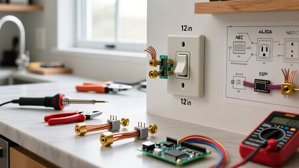
When you need to control two separate electrical circuits simultaneously with a single action, you are looking at a DPDT (Double Pole, Double Throw) configuration. But the term "switch" in electrical schematics can be a trap. It might refer to a manual 6-terminal toggle switch on a front panel, or an 8-pin electromechanical DPDT relay hidden inside a control enclosure. Wiring a DPDT switch correctly requires knowing exactly which device you have, what load it is driving, and how to protect the control circuit from inductive kickback.
This guide cuts through the ambiguity. We will break down the exact terminal mappings, decode the manufacturer rating columns that actually matter for your specific load, and provide a concrete decision path to select and test your component.
The Core Difference: Manual DPDT Switch vs. DPDT Relay
Before stripping wire, count your terminals. The physical architecture dictates your wiring strategy.
- Manual DPDT Toggle/Rocker Switch (6 Terminals): Features two common inputs (usually the center pins) and four outputs (two Normally Open, two Normally Closed). There is no coil. The actuator physically moves a wiper to route power. Used for direct human interface, like motor reversal or manual transfer switches.
- Electromechanical DPDT Relay (8 Terminals): Features two coil terminals (A1/A2 or pins 7/8) and six contact terminals (two COM, two NO, two NC). A low-voltage signal energizes the coil, creating a magnetic field that pulls the contacts closed. Used for PLC outputs, microcontroller isolation, and automated control panels.
Decoding the Ratings: Which Column Governs Your Load?
The most common mistake makers and junior technicians make is looking only at the "Max Amps" printed on the relay casing. A relay rated for 10A resistive might weld its contacts shut on a 3A motor load. You must match the utilization category to your load type.
| Device Type / Model | Coil Voltage | Contact Rating (AC-1 Resistive) | Contact Rating (AC-3 Motor) | Breaking Capacity |
|---|---|---|---|---|
| Carling 10A Manual Toggle | N/A (Manual) | 10A @ 125VAC | Not Rated (Avoid) | Low (No arc chute) |
| Omron G2R-2 (General Purpose) | 24VDC / 120VAC | 5A @ 250VAC | 2A @ 250VAC | Medium |
| Schneider TeSys LC1D09 | 24VDC / 240VAC | 25A (AC-1) | 9A (AC-3) | High (Arc chutes) |
Which column governs? If you are switching heaters or incandescent lights, use the AC-1 (Resistive) column. If you are switching compressors, fans, or pumps, you must use the AC-3 (Motor) column. Motors draw 6 to 10 times their running current during startup (Locked Rotor Amps). If your DPDT switch is only rated for AC-1, that inrush current will pit and eventually weld the contacts together.
Coil vs. Contact Wiring & Flyback Protection
When wiring a DPDT electromechanical relay, you are dealing with two entirely isolated circuits: the control side (coil) and the load side (contacts).
The Load Side (Contacts)
Wire your line voltage to the Common (COM) terminals. Wire your load to either the Normally Open (NO) or Normally Closed (NC) terminals depending on your failsafe requirements.
Crucial Breaker Note: Never treat fuses and breakers as interchangeable without checking the trip curve. If you are protecting the contact side of a DPDT relay driving a motor, you must use a C-curve or D-curve Miniature Circuit Breaker (MCB). A standard B-curve breaker will nuisance-trip instantly when the motor starts due to the inrush current. The breaker protects the wire; the relay contacts switch the load.
The Control Side (Coil) & Flyback Diodes
The coil is an inductor. When you apply DC voltage to pins A1 and A2, current builds a magnetic field. When you remove the voltage, the magnetic field collapses, inducing a massive reverse voltage spike (inductive kickback) that can easily exceed 100V.
If your DPDT relay coil is driven by a DC source (like an Arduino, ESP32, or PLC transistor output), you must wire a flyback diode (e.g., 1N4007) in reverse bias across the coil terminals. Wire the diode cathode (striped end) to the positive A1 terminal and the anode to the negative A2 terminal. Without this, the voltage spike will instantly destroy your microcontroller's GPIO pin or fry the PLC's output transistor. AC coils do not require this, as the alternating zero-crossing naturally extinguishes the arc.
Load Selection Decision Path
Use this decision tree to select the correct DPDT architecture for your specific application:
- IF the load is purely resistive (e.g., heating elements, LED lighting) AND under 10A → THEN a standard general-purpose DPDT relay (like the Omron G2R-2) or a manual toggle switch is sufficient.
- IF the load is inductive but non-motor (e.g., solenoid valves, contactor coils) → THEN use a DPDT relay with a high DC breaking capacity, and ensure you have RC snubbers across the load to prevent contact arcing.
- IF the load is a motor (e.g., HVAC blower, conveyor) AND exceeds 2A → THEN abandon standard PCB/DIN relays. You must use a heavy-duty DPDT contactor (like the Schneider TeSys series) designed specifically for AC-3 motor loads, paired with a thermal overload relay.
- IF you need manual reversal of a DC motor → THEN use a manual DPDT toggle switch (Center-Off configuration) rated for DC, wiring the COMs to the motor and the NO/NC terminals in an H-bridge crossover pattern.
How to Test a DPDT Switch: Dead and Live Diagnostics
Before troubleshooting a complex control panel, isolate the component. Here is the exact bench and field testing procedure.
Dead Testing (Power Off & Locked Out)
- Coil Resistance: Set your multimeter to Ohms (Ω). Measure across A1 and A2. A healthy 24VDC relay coil (like the Omron G2R) should read around 1,100Ω. If it reads infinite (OL), the internal coil wire is broken. If it reads near 0Ω, the coil is shorted.
- Contact Continuity: Set the meter to continuity (beep mode). Place probes on COM and NC. It should beep. Place probes on COM and NO. It should be silent.
For manual switches: Flip the actuator. The continuity states should perfectly swap.
Live Testing (Energized Circuit)
- Coil Voltage: With the circuit energized and the control signal active, measure AC or DC voltage across A1 and A2. It must be within ±10% of the nominal coil rating (e.g., 21.6V to 26.4V for a 24VDC coil). A brownout here will cause the relay to chatter and burn the contacts.
- Contact Voltage Drop: Measure the voltage between the COM terminal and the NO terminal while the relay is engaged and under load. A healthy contact will show a voltage drop of less than 0.1V. If you read 2V, 5V, or line voltage across closed contacts, the internal wiper is carbon-tracked or pitted. The switch is failing.
Repair vs. Replace: The Final Verdict and Default Pick
Electromechanical components are consumables. The mechanical life (millions of cycles without load) is vastly different from the electrical life (often under 100,000 cycles at full load). When a DPDT switch fails, do you repair or replace?
| Component Type | Failure Mode | Action Required |
|---|---|---|
| Manual Toggle Switch | Melted casing, loose actuator, pitted contacts | Replace. Never open a sealed manual switch to file contacts. |
| General Purpose Relay (<15A) | Coil burnout, welded contacts, high contact resistance | Replace. The cost of labor to diagnose exceeds the $8 part cost. |
| Heavy Duty Contactor (>20A) | Coil burnout | Repair. Coils on large contactors are often field-replaceable modules. |
| Heavy Duty Contactor (>20A) | Severely pitted/welded main contacts | Replace entire unit. Modern IEC contactors rarely have user-serviceable contact pads. |
For further reading on contactor lifecycle and replacement thresholds, refer to the Schneider Electric contactor maintenance guidelines and the Omron G2R series datasheet for exact electrical life expectancy curves.
The Default Recommendation
If you are building a 12V/24V DC control panel, an Arduino/ESP32 automated system, or upgrading a legacy PLC output, stop guessing with bare PCB relays. The Concrete Pick: Use the Phoenix Contact PLC-RSC- 24DC/21-21 (Part # 2912278). It is a DIN-rail mountable DPDT relay module with a 24VDC coil, plug-in relay socket, and integrated status LED. It costs roughly $22, handles 6A per contact, and most importantly, the socket base allows you to swap out the plug-in relay in three seconds without touching a screwdriver if the contacts eventually wear out. Pair it with a 1N4007 flyback diode on your DC drive side, use C-curve breakers on the load side, and your DPDT switching will run flawlessly for years.