
Anatomy of the NEMA 5-15P Plug
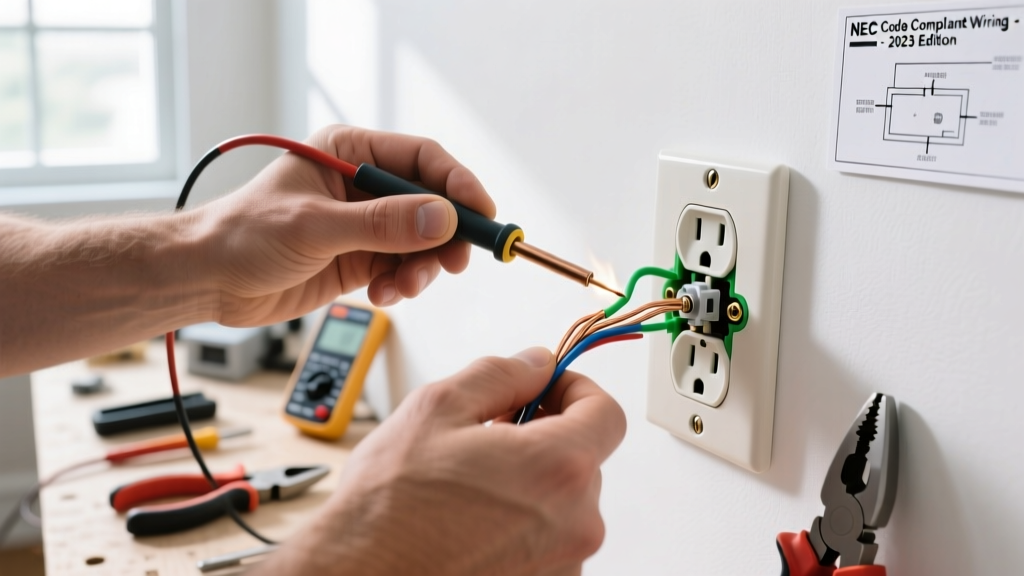
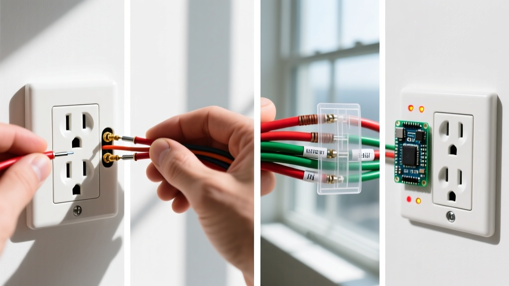
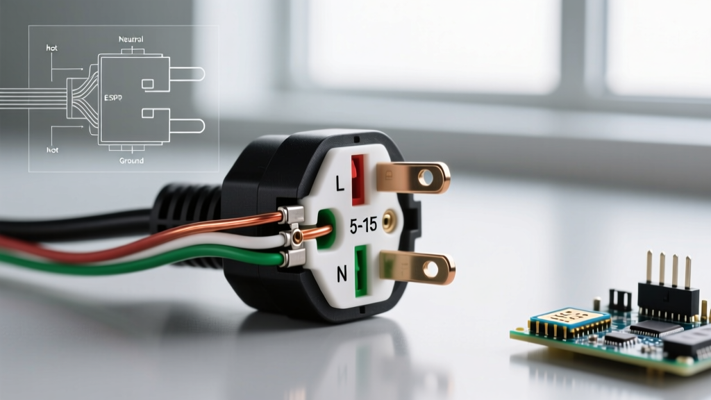
When referencing a standard North American 120V AC plug, you are working with a NEMA 5-15P configuration. This three-prong design is engineered to deliver up to 15 amps of current while providing a dedicated path to ground. Understanding the internal anatomy of the plug cap is the first step toward a safe, code-compliant termination.
Inside the plug housing, you will find three distinct terminal screws and a mechanical strain relief clamp. The terminal screws are color-coded and physically distinct to prevent polarity reversal:
- Brass Screw (Hot): Connects to the narrow blade of the plug. This carries the 120V alternating current from the breaker panel to the appliance.
- Silver Screw (Neutral): Connects to the wide blade. This provides the return path for the current back to the panel's neutral bus bar.
- Green Screw (Ground): Connects to the U-shaped or round pin. This is a safety shield that provides a low-resistance path to trip the breaker in the event of a fault.
Terminal Mapping & Wire Color Codes
For standard 120V flexible cords (such as SJOOW, SJTW, or SVT cables), the internal wire insulation follows a strict color code mandated by the National Electrical Code (NEC). Below is the definitive wiring diagram reference for mapping your cord wires to the NEMA 5-15P terminals.
| Wire Insulation Color | Terminal Screw Color | Plug Blade / Pin | Function |
|---|---|---|---|
| Black (or Red/Blue) | Brass | Narrow Flat Blade | Ungrounded Conductor (Hot) |
| White (or Gray) | Silver | Wide Flat Blade | Grounded Conductor (Neutral) |
| Green (or Bare Copper) | Green | Round / U-Shaped Pin | Equipment Grounding Conductor |
Hardware Selection: Standard vs. Industrial Grade
Not all replacement plugs are created equal. Selecting the right hardware impacts both the longevity of the connection and the physical safety of the user. In 2026, the market is dominated by two primary tiers of replacement plugs:
1. Residential / Standard Grade (e.g., Leviton 515-PV)
Priced between $2.50 and $4.00, these plugs feature a basic vinyl or thermoplastic shell. They utilize simple screw terminals and a lightweight internal strain relief bar. They are perfectly adequate for light-duty household items like desk lamps or clock radios but will degrade quickly if subjected to physical pulling or heavy vibration.
2. Industrial / Hospital Grade (e.g., Hubbell 515P5 or Bryant 515P)
Ranging from $6.00 to $12.00, industrial plugs feature heavy-duty nylon or polycarbonate shells, deep-recessed terminal screws to prevent accidental finger contact, and robust external cord clamps. Hospital-grade variants (marked with a green dot) undergo rigorous UL pull-tests and are required for medical equipment. For power tools, shop vacuums, or any appliance that is frequently moved, always specify an industrial-grade plug.
Step-by-Step Wiring Procedure
Proper preparation of the flexible cord is where most DIY failures occur. Follow these exact measurements to ensure a secure termination without compromising the copper stranding.
- Jacket Stripping: Using a cable ripper or a sharp utility knife, carefully slit the outer cord jacket back exactly 1.5 inches from the end. Do not score the internal wire insulation. Remove the exposed jacket and any paper or cotton filler strings.
- Conductor Stripping: Strip exactly 5/8 inch of insulation from the black, white, and green wires. Using precision wire strippers (such as the Klein Tools 11055) prevents nicking the copper strands. A nicked strand creates a localized hot spot under load, leading to premature failure.
- Forming the Shepherd's Hook: Twist the exposed copper strands tightly clockwise. Bend the wire into a tight 'U' shape or shepherd's hook. The hook must be sized so it wraps snugly around the terminal screw shaft without overlapping the insulation or extending past the screw head.
- The Clockwise Loop Rule: Always route the wire hook around the screw in a clockwise direction. As you tighten the screw with a flathead or Phillips driver (depending on the terminal type), the rotational force will pull the wire loop tighter around the shaft. A counter-clockwise loop will be pushed outward, resulting in a loose connection and potential arcing.
- Terminal Torque: Tighten the screws firmly until the brass or silver washer bottoms out. Give the wire a sharp tug to verify mechanical retention. Ensure no stray copper 'whiskers' are protruding from the terminal, as these can bridge the gap to adjacent terminals and cause a dead short.
The Strain Relief Mandate
The most frequently overlooked component in 3 prong electrical plug wiring is the strain relief clamp. According to OSHA standard 1910.304 regarding wiring design and protection, flexible cords must be protected from damage, which includes preventing tension from being transmitted directly to the terminal joints.
Expert Insight: The strain relief clamp must bite down exclusively on the outer rubber/vinyl jacket of the cord, never on the individual colored wires. If the clamp rests on the inner wires, it will eventually cut through the insulation, creating a severe shock hazard and a direct path for a ground fault.
Adjust the clamp screws evenly on both sides. If your cord is too thin for the plug's clamp (e.g., using a thin 18 AWG SVT lamp cord in a heavy-duty 14 AWG plug), you must wrap the jacket with high-quality friction tape to build up the diameter until the clamp grips securely without crushing the internal conductors.
Troubleshooting Matrix: Common Failure Modes
After assembling the plug, do not simply plug it in and hope for the best. Use a digital multimeter (DMM) or a dedicated receptacle tester to verify your work. Below is a diagnostic matrix for common wiring errors.
| Observed Symptom | Probable Wiring Error | Multimeter Verification Method |
|---|---|---|
| Breaker trips immediately upon plugging in | Hot and Ground shorted; or Hot and Neutral shorted due to copper whiskers. | Set DMM to Continuity/Ohms. Test between Narrow Blade and Round Pin. Should read 'OL' (Open Loop). Any low resistance indicates a short. |
| Appliance works, but chassis reads 120V with non-contact tester | Reversed Polarity (Black wire on Silver screw, White wire on Brass screw). | Test between Narrow Blade and Ground. If continuity exists, polarity is reversed. Swap the Black and White wires. |
| GFCI outlet trips when appliance is plugged in | Open Ground or Neutral-to-Ground fault downstream of the plug. | Verify continuity between the Round Pin and the appliance chassis. Check for stray neutral strands touching the green terminal. |
| Plug feels warm to the touch under load | Loose terminal screw; wire insulation trapped under the screw head; or undersized cord gauge. | Inspect visually. Ensure 12 AWG wire is used for 15A continuous loads and that the bare copper is fully under the screw head, not the insulation. |
NEC Compliance & Safety Standards
Adhering to the NFPA 70 National Electrical Code (NEC) is non-negotiable for both professional electricians and informed DIYers. Specifically, Article 406 covers receptacles, cord connectors, and attachment plugs. Furthermore, Article 250 outlines the strict requirements for grounding and bonding.
When wiring a 3-prong plug, remember that the grounding pin (the U-shaped prong) is physically longer than the current-carrying blades. This is a deliberate safety engineering feature: it ensures that the equipment ground is established before the hot and neutral connections make contact with the receptacle. Never file down, bend, or remove the grounding pin to fit an older 2-prong ungrounded receptacle. Doing so eliminates the fault-current path and violates NEC 250.148, exposing the user to lethal shock hazards in the event of an internal appliance short.
By following this diagram reference, utilizing the correct strip lengths, and enforcing the clockwise loop rule, you guarantee a robust, safe, and code-compliant termination that will withstand years of mechanical and electrical stress.