
The Role of Manual Overrides in Commercial Building Automation
As of 2026, the integration of microcontroller-based logic into commercial Building Automation Systems (BAS) has matured significantly. While hobbyists use basic development boards for simple DIY projects, commercial electrical contractors and industrial controls engineers increasingly deploy industrial-grade PLCs like the Arduino Opta 8X (ABX00072) for HVAC damper control, lighting dimming, and Variable Frequency Drive (VFD) speed overrides. A critical component in these systems is the manual override dial. When wiring potentiometer Arduino circuits for commercial environments, standard hobbyist practices fail due to electromagnetic interference (EMI), voltage drops, and strict code requirements. This guide details the professional methodology for integrating precision potentiometers into commercial control panels.
Selecting Commercial-Grade Components
In a commercial electrical panel, a standard carbon-track potentiometer will degrade rapidly due to temperature fluctuations, vibration from heavy contactors, and oxidation. You must specify cermet or wirewound precision potentiometers. The Bourns 3590S-1-103L (10kΩ, 3% tolerance, 2-watt wirewound) is an industry standard for BAS manual overrides, typically costing around $18.50 per unit. Unlike $1.50 hobby pots with a 10,000-cycle rotational life, the Bourns 3590 series offers 5 million shaft revolutions and a temperature coefficient of ±50 ppm/°C.
Component Comparison: Hobby vs. Commercial
| Feature | Standard Carbon Pot (e.g., Alpha 10k) | Precision Wirewound (e.g., Bourns 3590S) |
|---|---|---|
| Resistance Tolerance | ±20% | ±3% |
| Rotational Life | ~10,000 cycles | ~5,000,000 cycles |
| Power Rating | 0.125W | 2.0W |
| Temp Coefficient | ±1000 ppm/°C | ±50 ppm/°C |
| Typical Unit Cost | $1.20 | $18.50 |
Step-by-Step: Wiring Potentiometer Arduino Opta for VFD Control
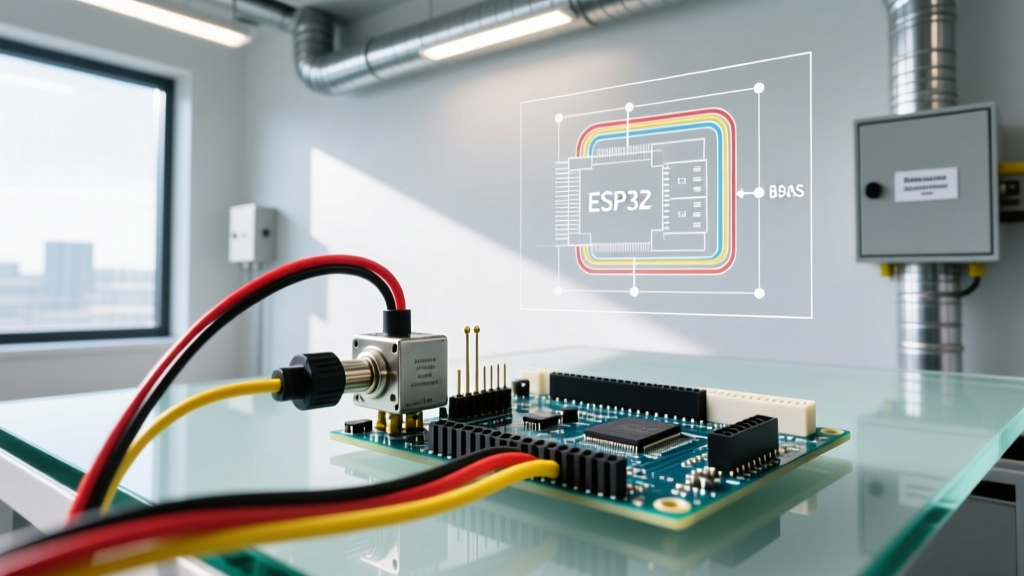
When wiring a potentiometer to an Arduino Opta for scaling a 0-10V analog output to a Yaskawa GA800 VFD, signal integrity is paramount. The Opta features isolated analog inputs and a dedicated 24V DC industrial power supply, but the 5V reference used for the potentiometer must be meticulously managed.
1. Power and Reference Voltage Isolation
Never power a commercial potentiometer directly from a shared 5V rail that also powers relays or indicator LEDs. Switching loads cause micro-second voltage sags that translate directly into analog read jitter. Instead, use a dedicated low-noise Linear Dropout (LDO) regulator, such as the Texas Instruments LP2951, to step down the Opta’s internal logic voltage to a pristine 5.00V reference exclusively for the sensor network. Connect the LDO output to Pin 3 (CW) of the Bourns potentiometer.
2. Signal Wiring and Shielding
Commercial control panels require shielded twisted-pair (STP) cabling for all analog signals. We specify Belden 8760 (18 AWG, shielded twisted pair, approx. $1.20/ft).
- Black Wire (Pair 1): Connect to the Wiper (Pin 2) and route to Arduino Opta Analog Input A0.
- Clear Wire (Pair 1): Connect to Signal Ground (AGND).
- Drain Wire (Shield): Connect to the panel chassis ground bus bar at one end only. Grounding both ends creates a ground loop, which will induce 60Hz hum from adjacent line-voltage wiring.
3. Hardware Noise Filtering (RC Low-Pass)
In environments with heavy VFDs, high-frequency switching noise (often between 2 kHz and 16 kHz) can alias into the Arduino’s Analog-to-Digital Converter (ADC). To mitigate this, solder a hardware RC low-pass filter directly at the Arduino terminal block. Place a 100Ω metal film resistor in series with the wiper signal, and a 100nF (0.1µF) X7R ceramic capacitor between the ADC pin and AGND. This creates a cutoff frequency ($f_c$) of approximately 15.9 kHz, effectively shorting high-frequency EMI to ground before it reaches the microcontroller.
⚠️ NEC Article 725 Compliance Warning:
When routing low-voltage BAS control wiring inside commercial panels, you must adhere to NFPA 70 (National Electrical Code) Article 725. Class 2 and Class 3 circuit conductors must be physically separated from Class 1 line-voltage conductors (120V/480V) by at least 2 inches, or separated by a grounded metal barrier. Failure to maintain this separation will result in a failed municipal electrical inspection and severe inductive noise on your analog signals.
Software Calibration for Industrial 0-10V Scaling
Once the hardware is wired, the Arduino Opta must map the 12-bit ADC reading (0-4095) to a commercial 0-10V control signal. Because mechanical hard-stops on precision pots rarely align perfectly with electrical zero, commercial firmware utilizes a software deadband and calibration routine.
According to the official Arduino Opta documentation, the analog inputs are highly linear, but mechanical backlash requires a moving average filter in the firmware to prevent actuator hunting. Implement an Exponential Moving Average (EMA) in your C++ loop:
float rawADC = analogRead(A0);
float filteredADC = (0.1 * rawADC) + (0.9 * previousADC);
previousADC = filteredADC;
// Map 12-bit to 0-10V DAC output
int dacValue = map(filteredADC, 50, 4045, 0, 4095);
analogWrite(DAC0, constrain(dacValue, 0, 4095));
This EMA filter (alpha = 0.1) heavily weights historical data, smoothing out physical vibrations transferred to the potentiometer shaft from the control panel door.
Environmental Sealing and Panel Mounting
In commercial applications like food processing plants or outdoor pump stations, control panels are rated NEMA 4X or IP65. Standard potentiometer shafts will allow moisture ingress. You must specify potentiometers with IP65-rated shaft seals, or use a Vishay 534 series potentiometer housed in a sealed NEMA 4X polycarbonate operator station (e.g., Eaton Crouse-Hinds EFS series enclosures, approx. $145.00). Ensure the locking nut is torqued to the manufacturer's specification (typically 1.5 Nm) using a specialized spanner wrench to prevent cracking the phenolic housing.
Troubleshooting Signal Drift in High-EMI Environments
Even with perfect wiring, commercial environments present unique failure modes. If your Arduino reads erratic values, consult this diagnostic matrix:
| Symptom | Probable Cause | Commercial Solution |
|---|---|---|
| Value drifts slowly over 10-15 minutes | Thermal drift in carbon pot or voltage reference | Upgrade to wirewound Bourns precision pot and LDO reference. |
| Random high-amplitude spikes (±200 ADC) | Capacitive coupling from adjacent 480V VFD cables | Verify Belden 8760 shield is grounded at one end; increase physical separation. |
| Signal drops to zero intermittently | Wiper contact bounce due to panel vibration | Replace single-turn pot with a 10-turn Bourns 3590 series; add hardware RC filter. |
| Consistent offset error (e.g., reads 100 at zero) | Ground potential difference between Opta and sensor | Implement a star-ground topology; tie AGND to chassis at a single master lug. |
Final Commissioning Checklist
Before energizing the commercial panel, verify the following:
- Megger Test: Ensure shielded cables have not been pinched during panel routing, which would short the shield to the signal wire.
- Vref Verification: Measure the voltage at Pin 3 of the potentiometer with a Fluke 87V multimeter. It must read exactly 5.00V DC (±0.01V) with all panel contactors energized.
- Deadband Check: Rotate the dial to physical zero and physical max. Ensure the software deadband prevents the VFD from receiving a negative or over-voltage command.