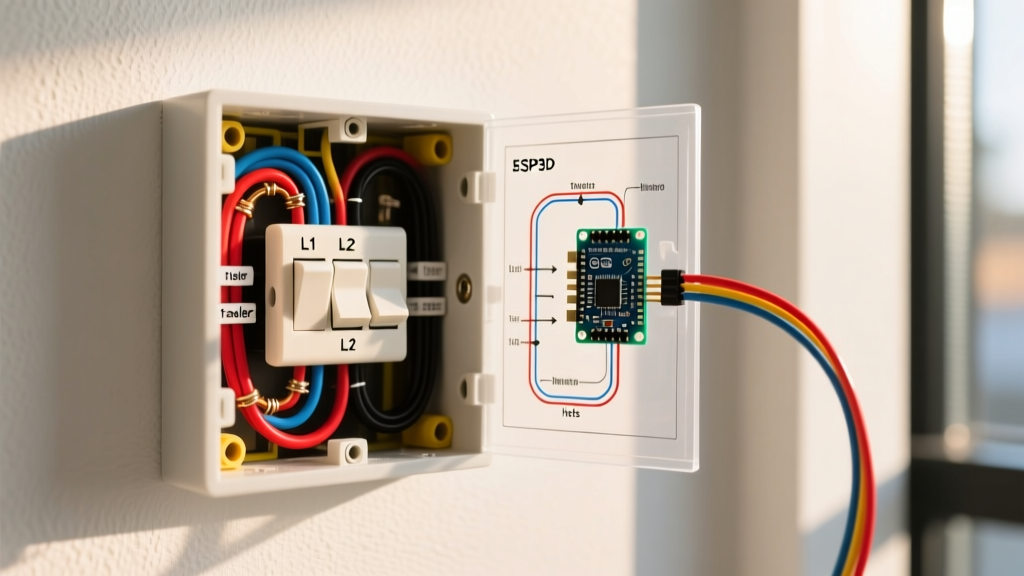

The Code-First Approach to 3-Way Switching
When homeowners and even some apprentice electricians search for a wiring for 3 way switch diagram, they are usually met with simplified illustrations that completely ignore the National Electrical Code (NEC). While a basic schematic might show you how to complete a circuit and illuminate a bulb, it rarely addresses the stringent safety, box fill, and grounding mandates enforced by your local Authority Having Jurisdiction (AHJ). In 2026, electrical inspectors are stricter than ever regarding switch loop configurations, particularly concerning neutral conductor requirements and proper grounding pathways.
Understanding the intersection between theoretical circuit diagrams and practical NEC compliance is the difference between a safe, future-proof installation and a failed inspection. According to the National Fire Protection Association (NFPA), the NEC is updated every three years to address emerging fire hazards and new technology loads. This guide breaks down the exact code standards you must apply when executing a 3-way switch installation.
NEC 404.2(C): The Neutral Conductor Mandate
The most significant shift in modern switch wiring revolves around the neutral wire. Historically, a standard switch loop only required a hot and a switched hot (or two travelers and a common). The white wire in a 14/2 or 12/2 NM-B cable was routinely re-identified with black tape and used as a hot conductor.
NEC 404.2(C) Switches Controlling Lighting Loads: Where lighting loads are controlled by snap switches, a neutral conductor must be provided at the switch box. This is to accommodate smart switches, timers, and occupancy sensors that require a continuous 120V reference to power their internal electronics.
When planning your wiring for 3 way switch diagram, you must run a 3-conductor cable with a ground (e.g., Southwire 14/3 NM-B or 12/3 NM-B) to at least one of the switch boxes to ensure a dedicated neutral is present. Relying on the equipment grounding conductor (EGC) to carry neutral current for a smart switch is a severe code violation and a major shock hazard, as noted in OSHA electrical safety guidelines.
Box Fill Calculations: Sizing Your Junction Boxes
A common failure point in 3-way installations is overcrowding the electrical box. NEC Article 314 dictates strict volume allowances to prevent wire insulation damage and overheating. When mapping out your wiring for 3 way switch diagram, you must calculate the box fill before purchasing materials.
NEC Chapter 9, Table 314.16(B) Volume Allowances
| Item to Count | Quantity per 3-Way Box | 14 AWG Multiplier (cu in.) | 12 AWG Multiplier (cu in.) |
|---|---|---|---|
| Hot/Neutral Conductors entering/leaving | 3 to 4 | 2.0 per wire | 2.25 per wire |
| Equipment Grounds (All combined) | 1 | 2.0 | 2.25 |
| Internal Cable Clamps | 1 (if present) | 2.0 | 2.25 |
| Device (The 3-Way Switch itself) | 2 (Double volume) | 4.0 | 4.5 |
Real-World Example: If you are wiring a 3-way switch box with one 14/2 feed and one 14/3 traveler cable using 14 AWG wire, your calculation looks like this: 5 current-carrying conductors (10 cu in) + 1 ground (2 cu in) + 1 clamp (2 cu in) + 1 device (4 cu in) = 18 cubic inches minimum. You would need a deep box like the Carlon B618R (18 cu in. PVC) or a standard 1900 metal box. Using a standard 14 cu in. shallow blue plastic box will result in an immediate code violation.
Traveler Routing and Terminal Identification
A standard 3-way switch features three terminals: one 'Common' (usually a dark-colored screw) and two 'Travelers' (usually brass-colored screws). The NEC does not strictly mandate specific color coding for traveler wires, but industry standards and National Electrical Manufacturers Association (NEMA) best practices strongly dictate the following color scheme to ensure safe troubleshooting:
- Black: Line voltage (Hot) or Common load feed.
- Red & Black (in 3-conductor cable): Traveler wires connecting the two switches.
- White: Dedicated Neutral (must remain white, never re-identified as hot in modern switch loops).
- Bare/Green: Equipment Grounding Conductor (EGC).
Pro-Tip: Identifying the Common Terminal
Never assume the physical position of the dark screw is identical across brands. A Leviton Decora 3-way switch may have the common screw on the bottom right, while a Lutron Maestro smart 3-way switch might place it on the top left. Always use a non-contact voltage tester or a digital multimeter (like the Klein Tools MM400) to verify the line-hot conductor before attaching it to the common terminal.
Smart 3-Way Switches: Code Meets Technology
If your wiring for 3 way switch diagram includes smart home integration, the physical wiring topology changes drastically. Traditional mechanical 3-way switches use travelers to physically route the current. Smart switches, however, often use wireless communication or low-voltage signaling between a master switch and a remote companion.
Comparison: Mechanical vs. Smart 3-Way Topologies
| Feature | Mechanical 3-Way (e.g., Eaton 1353W) | Smart 3-Way (e.g., Lutron Caseta PD-5S-DV) |
|---|---|---|
| Traveler Wires Required | Yes (Red and Black) | No (Travelers capped or repurposed) |
| Neutral Wire Required | No (But NEC 404.2(C) mandates it in box) | Yes (Required for internal radio/Wi-Fi) |
| Box Depth Needed | Standard (14-18 cu in) | Deep (18-22 cu in) due to bulky wire harness |
| Grounding | Standard EGC pigtail | Standard EGC (Critical for RF shielding) |
When installing smart switches like the Leviton Decora Smart DW3HL, the wire harness and bulky WAGO connector blocks require significant physical space. Always upgrade to a 22 cu in. deep box during rough-in if you anticipate smart home upgrades.
Common Code Violations and Inspection Failures
Even with a perfect schematic on paper, physical execution often leads to code violations. Avoid these frequent AHJ red flags:
- The 'Bootleg' Ground: Connecting the neutral and ground terminals together at the switch to trick a receptacle tester. This creates a parallel neutral path on the ground wire, energizing all metal faceplates in the circuit.
- Missing Grounding Pigtails: Metal boxes require the metal box itself to be grounded, in addition to the switch yoke. You must use a green grounding screw and a 14 AWG or 12 AWG bare copper pigtail to bond the box to the circuit ground.
- Over-torqued Terminal Screws: Wrapping 12 AWG solid copper wire around a 15A switch terminal designed for 14 AWG can cause the screw to strip or the wire to deform, creating a high-resistance connection that generates excessive heat over time.
- Exposed Copper at Terminals: Stripping too much insulation leaves bare copper exposed outside the switch terminal. The NEC requires that no bare, un-insulated current-carrying conductor be exposed to accidental contact.
Frequently Asked Questions (FAQ)
Can I use a 14/2 cable between the two 3-way switches?
No. A 14/2 cable only provides a black, white, and bare wire. You need a minimum of two traveler wires and a common wire between the switches, which requires a 14/3 cable (black, red, white, bare). Using 14/2 would force you to use the ground wire as a current-carrying traveler, which is a severe NEC violation and a lethal shock hazard.
Do I need to pigtail the grounds if I'm using a plastic box?
Yes. While plastic (non-metallic) boxes do not require bonding to the ground wire, the 3-way switch itself has a green grounding screw that must be connected to the circuit's equipment grounding conductor. Use a wire nut or a WAGO 221 lever-nut to connect the incoming ground, the outgoing ground, and a 6-inch pigtail leading to the switch.
What happens if I swap the line and load on a 3-way switch?
On a traditional mechanical 3-way switch, swapping line and load will usually still allow the circuit to function, as the switch simply bridges the common to the travelers regardless of current direction. However, on smart switches or AFCI/GFCI protected circuits, swapping line and load will cause the device to malfunction, fail to reset, or trip the breaker immediately due to improper sensor orientation.