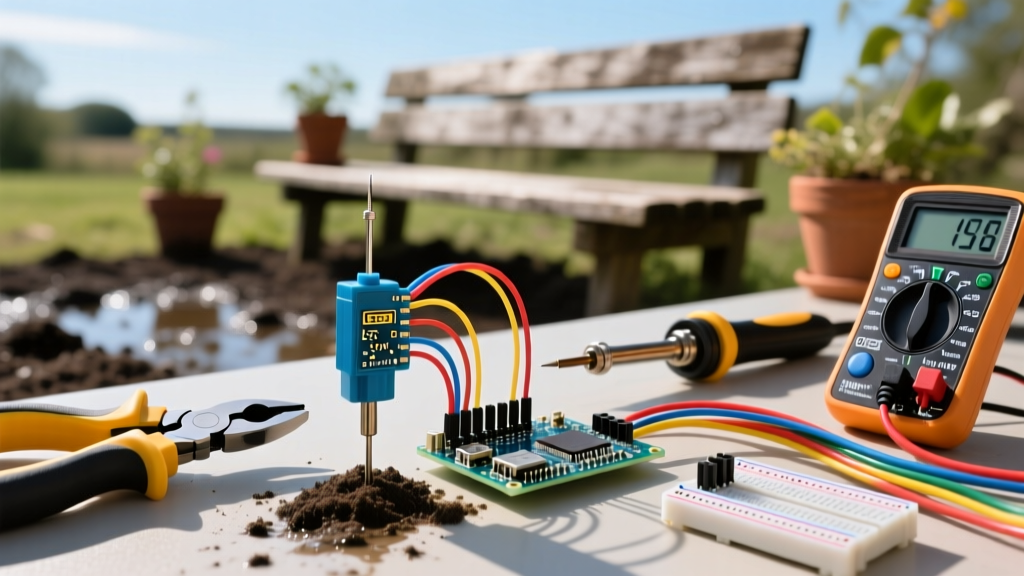

Material Selection: The Corrosion Factor
The most common point of failure in DIY irrigation electronics is not the code, but the sensor material. Standard resistive sensors (like the generic YL-69) pass a small current through the soil to measure resistance. This triggers rapid galvanic corrosion, dissolving the nickel plating within weeks and rendering the sensor useless.
Capacitive Sensors: The Professional Standard
For any permanent installation, you must use capacitive sensors. Models like the Adafruit 4026 or DFRobot SEN0193 (typically priced between $6 and $9) measure changes in dielectric permittivity rather than electrical conductivity. Because the electrodes are sealed and do not pass direct current through the soil, they are immune to galvanic corrosion. When sourcing materials, ensure the sensor's conformal coating extends fully down the PCB to prevent water ingress at the component joints.
The Distance Problem: Signal Degradation Over Long Runs
A critical mistake beginners make is running 50 feet of standard jumper wire from an analog capacitive sensor back to the Arduino's ADC (Analog-to-Digital Converter) pins. Analog voltage signals (0-3.3V or 0-5V) are highly susceptible to electromagnetic interference (EMI) and voltage drop over long, unshielded wire runs. A 50-foot run of 22 AWG wire can easily introduce enough resistance and noise to skew your moisture readings by 20% or more.
Expert Wiring Tip: If your sensor must be located more than 15 feet from the microcontroller, abandon analog output entirely. Instead, use an I2C-enabled moisture sensor or place a secondary Arduino Nano in a weatherproof enclosure near the sensor, transmitting digital data back to the main controller via RS-485 transceivers (like the MAX485 module) over twisted-pair Cat5e cable.
Essential Wiring Materials & Tool Matrix
Deploying a robust ground moisture sensor Arduino network requires specific electrical materials rated for wet, subterranean environments. Below is the definitive checklist for a professional-grade installation.
| Category | Specific Material / Tool | Purpose & Specification | Est. Cost (2026) |
|---|---|---|---|
| Primary Cable | Southwire 18/5 Direct Burial Sprinkler Wire | UV and moisture resistant jacket; 5 conductors for VCC, GND, and multiple sensor data lines. | $45 / 250ft |
| Splicing | Gardner Bender Gel-Filled Wire Connectors | Internal dielectric grease displaces water; rated for direct burial up to 18 AWG. | $12 / 50-pack |
| Enclosure | Bud Industries NEMA 4X Polycarbonate Box | IP66 rated; protects the Arduino and relay modules from hose spray and heavy rain. | $28 - $40 |
| Wire Prep | Klein Tools 11063W Wire Strippers | Prevents nicking the copper strands on 18-22 AWG stranded wire, which causes breakage underground. | $22 |
| Testing | Fluke 117 True RMS Multimeter | Essential for verifying voltage drop at the end of long trench runs before backfilling. | $195 |
Waterproofing and Direct Burial Protocols
Water is the enemy of low-voltage DC wiring. Even direct burial cables can fail if water wicks into the copper strands at the termination points, leading to short circuits and erratic sensor behavior. Proper waterproofing is non-negotiable.
Step-by-Step Termination and Trenching
- Prepare the Sensor Pigtail: Solder a 12-inch pigtail of 22 AWG stranded silicone wire directly to the capacitive sensor's header pins. Do not rely on friction-fit Dupont connectors outdoors; they will oxidize and fail.
- Apply Marine Heat Shrink: Slide dual-wall, adhesive-lined marine heat shrink tubing over the solder joints. When heated, the inner lining melts and creates a watertight seal against the PCB and wires.
- Encapsulate the Board: Submerge the sensor's PCB (excluding the sensing prongs) in a potting compound like MG Chemicals Silicone Encapsulant. This provides a secondary barrier against soil acidity and moisture.
- Execute the Splice: Connect the sensor pigtail to your main 18/5 direct burial cable using the gel-filled wire connectors. Twist the stripped wires together, push them firmly into the gel cap, and twist until the internal blade makes contact.
- Trenching Depth: According to standard landscaping practices and NFPA 70 (National Electrical Code) guidelines for Class 2 low-voltage circuits, bury the cable at least 6 inches deep in garden beds. If running under a lawn subject to aeration, increase depth to 12 inches or run the wire through 1/2-inch Schedule 40 PVC conduit to prevent shovel and aerator damage.
High-Voltage Isolation: Triggering 24V Solenoids
The ultimate goal of a ground moisture sensor Arduino project is usually to automate irrigation valves. Standard residential sprinkler valves operate on 24V AC, while the Arduino operates on 5V DC. You must bridge this gap safely without frying the microcontroller.
Never connect the Arduino's GPIO pins directly to a relay coil without protection. Use an opto-isolated relay module (such as the SainSmart 8-Channel 5V Relay). The optical isolator ensures that if a voltage spike occurs on the 24V AC solenoid side—common when inductive loads like solenoid coils are switched off—it cannot travel back through the relay coil and destroy your Arduino's ATmega328P or ESP32 chip. Always wire a flyback diode (like a 1N4007) in reverse parallel across the solenoid coil to suppress inductive kickback.
Code Compliance and System Grounding
While low-voltage sensor wiring is generally exempt from strict NEC conduit requirements, the integration with your main irrigation controller and AC power requires attention to safety. The 24V AC transformer powering your relays and solenoids must be properly grounded. According to agricultural engineering guidelines from Penn State Extension, properly installed soil moisture sensors not only save water but require robust physical protection to survive seasonal freeze-thaw cycles.
When mounting your NEMA 4X enclosure containing the Arduino and relays, ensure it is attached to a stable post or the side of a structure, with the cable entry glands pointing strictly downward. This creates a 'drip loop' in the wiring, preventing rainwater from tracking along the cable jacket and directly into your enclosure. For a deeper dive into sensor calibration across different soil types, refer to the Adafruit Capacitive Soil Moisture Sensor Guide, which provides excellent baseline code and hardware integration strategies.
Final Verification Before Backfilling
Before covering your trenches and sealing your enclosures, power the system and perform a live continuity and voltage test. Use your multimeter to verify that the Arduino is receiving a stable 5V at the enclosure, and that the analog or I2C data lines are returning expected values when the sensor is placed in a cup of dry soil versus saturated soil. Only after confirming stable data transmission and successful relay actuation should you backfill the trench and compact the soil. A well-wired ground moisture sensor Arduino system, built with the right materials and burial techniques, will provide years of autonomous, water-saving irrigation control.