
Conduit electrical wiring is far more than simply pushing cables through hollow tubes. It is a strict mathematical and mechanical discipline governed by the National Electrical Code (NEC). Whether you are running power to a new subpanel in a residential garage or routing feeders through a commercial manufacturing plant, violating conduit fill or bending rules can lead to catastrophic insulation failure, overheating, and failed inspections. As jurisdictions across the country continue to adopt and enforce the NEC 2023 standards through 2026, understanding the precise code requirements for raceway installations is mandatory for any serious electrician or advanced DIYer.
Decoding Conduit Types and NEC Article Assignments
The NEC categorizes raceways by material, thickness, and environmental suitability. Selecting the wrong conduit type for a specific environment is a common code violation. Below is a breakdown of the most common conduit types used in modern conduit electrical wiring, their governing NEC Articles, and current approximate material costs for 3/4-inch trade size.
| Conduit Type | NEC Article | Primary Use Case | Avg. Cost (3/4") |
|---|---|---|---|
| EMT (Electrical Metallic Tubing) | Article 358 | Indoor, dry locations, exposed commercial walls | $0.45 / ft |
| PVC Schedule 40 | Article 352 | Underground direct burial, corrosive environments | $0.30 / ft |
| PVC Schedule 80 | Article 352 | Above ground where subject to physical damage | $0.65 / ft |
| IMC (Intermediate Metal Conduit) | Article 345 | Industrial, outdoor, requires less threading than RMC | $1.40 / ft |
| RMC (Rigid Metal Conduit) | Article 344 | Heavy industrial, extreme physical protection | $2.10 / ft |
The 40% Rule: Mastering Conduit Fill Capacity
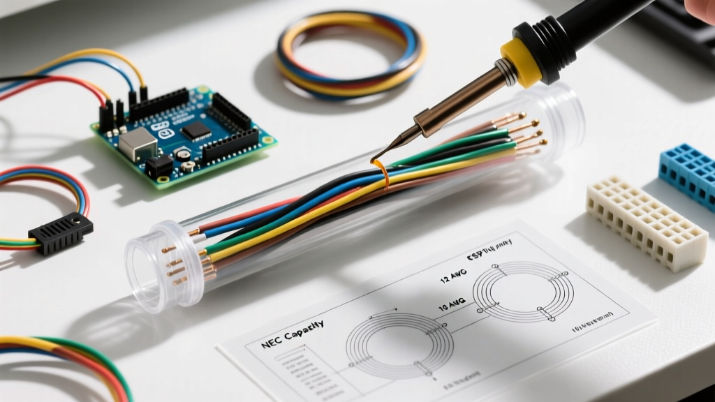
The most frequently cited violation in conduit electrical wiring is overfilling the raceway. The NEC mandates strict limits on how much of the conduit's internal cross-sectional area can be occupied by conductors. This is not arbitrary; it ensures adequate heat dissipation and prevents excessive pulling tension that can stretch copper or tear insulation.
According to NEC Chapter 9, Table 1, the maximum fill capacities are:
- 1 Conductor: 53% of the conduit's internal area.
- 2 Conductors: 31% of the conduit's internal area.
- 3 or more Conductors: 40% of the conduit's internal area.
Calculating Fill for Mixed Conductor Sizes
When pulling identical wire sizes, you can rely on NEC Chapter 9, Table C.1 (for EMT) or Table C.9 (for PVC). However, when mixing wire sizes—such as pulling three 4 AWG THHN ungrounded conductors and one 8 AWG THHN equipment grounding conductor—you must perform a manual calculation using Chapter 9, Table 4 (Conduit Dimensions) and Table 5 (Conductor Dimensions).
Example Calculation: You are using 1-inch EMT. The total internal area is 0.864 sq. in. At 40% fill, your maximum allowable wire area is 0.346 sq. in. A 4 AWG THHN wire has an area of 0.0824 sq. in. Three of them equal 0.2472 sq. in. An 8 AWG THHN wire has an area of 0.0366 sq. in. The total combined area is 0.2838 sq. in., which is well under the 0.346 sq. in. limit. This pull is code-compliant.
Bending Limits, Pull Points, and the Jam Ratio
Pulling wire through conduit generates friction and mechanical stress. To prevent installers from creating impossible friction traps, the NEC strictly limits the number of bends allowed between pull points. According to NEC 358.24 (for EMT) and similar sections for other raceways, there shall be no more than the equivalent of four quarter bends (360 degrees total) between pull points such as boxes, cabinets, or conduit bodies.
Expert Warning: The Jam Ratio
Even if your conduit fill is under 40%, you can still fail a pull due to the 'Jam Ratio.' When pulling three or more cables through a bend, if the ratio of the conduit's inside diameter (ID) to the cable's outside diameter (OD) falls between 2.8 and 3.2, the cables will wedge against each other and jam at the bend. Always calculate the jam ratio before pulling parallel feeders through sweeps.
If your run requires more than 360 degrees of bending, you must install an accessible pull box or conduit body (like an LB or LL) to break up the run. Furthermore, NEC 300.34 requires that the radius of the bend must not be less than the values specified in Table 300.34 to prevent kinking or damaging the insulation during the pull.
Securing and Supporting Distances by Material
Conduit must be securely fastened to the building structure to prevent sagging, which can alter the internal geometry of the raceway and stress the fittings. Support intervals vary drastically based on the material and trade size. According to the National Fire Protection Association (NFPA) code text, standard support rules include:
- EMT (Article 358.30): Must be secured within 3 feet of every outlet box, junction box, or fitting, and at intervals not exceeding 10 feet.
- PVC Schedule 40/80 (Article 352.30): Support intervals depend on trade size. 1/2-inch through 1-inch PVC must be supported every 3 feet. 1-1/4-inch through 2-inch must be supported every 5 feet. 2-1/2-inch and larger require support every 6 feet.
- RMC and IMC (Articles 344.30 / 345.30): Generally require support every 10 feet, with specific allowances for 14-foot intervals in certain exposed industrial joist setups.
Grounding and Bonding: The Metal Conduit Advantage
One of the primary advantages of metal conduit electrical wiring (EMT, IMC, RMC) is that the raceway itself can serve as the Equipment Grounding Conductor (EGC). Under NEC 250.118, listed metal raceways are approved as EGCs, provided they are installed with listed fittings and the connections are tight.
However, as industry experts at EC&M frequently point out, relying on the conduit for grounding requires strict attention to mechanical continuity. Set-screw couplings for EMT must be tightened until the screw head breaks off or is fully seated. If you are using flexible metal conduit (FMC) or liquidtight flexible metal conduit (LFMC), the NEC limits their use as a grounding path to specific lengths (typically 6 feet) and amperage limits, often requiring a separate copper grounding wire to be pulled inside the flex.
Troubleshooting Edge Cases: When Wire Pulling Fails
Even with perfect math and code compliance, physical pulls can fail. Here is how to troubleshoot common edge cases in the field:
- Excessive Pulling Tension: If the wire stretches or the insulation tears, your pulling tension has exceeded the manufacturer's limit (typically 0.008 lbs per circular mil for copper). Use a pulling compound (wire lube) rated for the specific insulation type (e.g., THHN vs. XHHW-2) to reduce the coefficient of friction.
- Conduit Sweating and Moisture: In underground PVC runs transitioning into climate-controlled buildings, temperature differentials cause condensation inside the conduit. This can lead to corrosion or insulation breakdown. Always use duct seal at the conduit ends and install a drip loop or condensation fitting where the raceway enters the panel.
- Thermal Expansion in PVC: PVC expands and contracts significantly with temperature changes (approx. 4 inches per 100 feet for a 100°F temperature swing). For long outdoor runs of conduit electrical wiring, NEC 352.44 mandates the use of expansion fittings to prevent the conduit from buckling or tearing out of the glued joints.
Mastering conduit electrical wiring requires moving beyond basic installation and embracing the engineering principles embedded in the NEC. By strictly adhering to fill capacities, respecting bending limits, and ensuring proper support and bonding, you guarantee a safe, inspectable, and long-lasting electrical infrastructure.