
The Rise of Remote Electrical Diagnostics in 2026
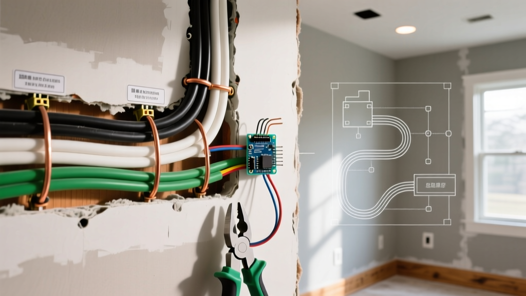
The electrical service industry has undergone a massive shift toward tele-diagnostics. With master electricians charging between $125 and $175 per hour for remote consultations in 2026, the ability to capture, share, and analyze high-quality electrical wiring photos is no longer just a documentation tool—it is a critical troubleshooting methodology. Whether you are a homeowner trying to understand why a breaker keeps tripping, or an apprentice sending panel shots to a journeyman for guidance, the clarity of your images dictates the accuracy of the diagnosis.
According to the U.S. Consumer Product Safety Commission (CPSC), electrical malfunctions remain a leading cause of residential fires. Many of these hazards, such as loose terminations, overloaded neutrals, and improper bonding, are entirely visible in photographs if captured with the right technique. This guide will teach you how to transform a standard smartphone camera into a professional diagnostic instrument.
Essential Gear for Capturing Diagnostic-Grade Photos
You do not need a $3,000 DSLR to take actionable electrical wiring photos, but you do need to understand lighting and focal lengths. The most common mistake amateurs make is using the built-in smartphone flash, which creates a harsh specular reflection on bare copper wire and glossy panel labels, completely washing out the text.
- Smartphone Macro Capabilities: Modern flagships like the iPhone 16 Pro or Samsung Galaxy S24 Ultra feature dedicated 48MP macro modes. These allow you to focus at a distance of just 2 inches, which is crucial for reading the micro-stamping on THHN insulation (e.g., '12 AWG CU 600V') or checking for torque seal marks on breaker lugs.
- Off-Axis Lighting: Use a 5000K daylight LED work light. Position the light at a 45-degree angle to the panel. This raking light eliminates glare on copper conductors and highlights physical defects like nicked insulation or crushed wire strands.
- Polarizing Filters: A $25 clip-on polarizing filter for your smartphone lens can cut through the glare of overhead fluorescent shop lights, allowing you to clearly read the faded ink on a 20-year-old Square D Homeline panel schedule.
The 3-Shot Protocol for Panel Documentation
When sending electrical wiring photos to a remote expert, a single wide shot is never enough. Professionals use a standardized three-shot protocol to ensure all diagnostic data is captured without requiring a second site visit.
- Shot 1: The Context Shot (Wide Angle). Stand exactly three feet back from the panel. Capture the entire dead-front removed, showing the main breaker, the overall wire dressing, and the panel manufacturer label. This shot reveals macro-issues like rust intrusion, missing knockouts, and general 'rats nest' wiring violations under NEC 110.12 (Mechanical Execution of Work).
- Shot 2: The Topology Shot (Medium Angle). Focus specifically on the neutral and ground bus bars. In subpanels, these must be isolated. This shot allows the diagnosing electrician to verify that neutral conductors are not improperly landing on the equipment grounding bar, a frequent cause of nuisance GFCI trips and objectionable neutral current.
- Shot 3: The Termination Macro (Close-Up). Zoom in on the specific breaker or lug in question. You are looking for 'push-past' errors (where the wire insulation is stripped too far, leaving bare copper exposed outside the lug) or 'under-insertion' (where the insulation is caught under the torque screw, creating a high-resistance connection).
5 Critical Code Violations to Spot in Panel Photos
When reviewing electrical wiring photos, train your eye to look for these specific, high-risk violations. The National Fire Protection Association (NFPA 70 / NEC) strictly prohibits these practices due to their direct correlation with arc faults and thermal runaway.
| Defect | Visual Cue in Photo | NEC Reference | Risk Level |
|---|---|---|---|
| Double-Tapped Lugs | Two distinct wires inserted under a single breaker screw not explicitly rated for two conductors. | 110.14(A) | High (Fire) |
| Overcrowded Neutral Bar | More than one neutral wire terminated under a single lug hole on the bus bar. | 408.41 | High (Shock/Fire) |
| Missing MWBC Handle Ties | Two adjacent single-pole breakers feeding a 3-wire cable without a physical approved handle tie. | 210.4(B) | Critical (Lethal Shock) |
| Subpanel Bonding | A green #10-32 bonding screw or copper bonding strap connecting the neutral bar to the panel enclosure in a subpanel. | 250.142(B) | High (Shock) |
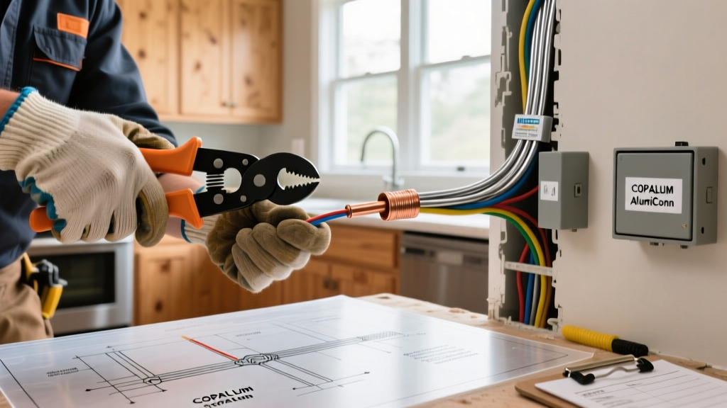
| Aluminum/Copper Mixing | Bare aluminum wire landed on a breaker not marked 'CO/ALR' or 'CU/AL', or mixed directly with copper under one lug. | 110.14 | Critical (Fire) |
Thermal Imaging: Seeing the Invisible Faults
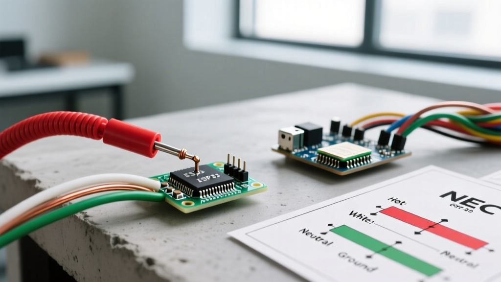
Standard photography only captures the visible spectrum. To troubleshoot high-resistance connections that are actively generating heat, you must integrate thermal electrical wiring photos into your diagnostic workflow. Tools like the Teledyne FLIR C5 ($549) or the Flir One Pro smartphone attachment ($249) are indispensable in 2026.
Pro Tip: When taking thermal photos of a panel, you must adjust the 'emissivity' setting in your app. Bare, shiny copper has an emissivity of roughly 0.1, which will reflect ambient room heat and give false readings. Wrap a small piece of black electrical tape (emissivity 0.95) around the wire near the termination, and aim your thermal camera at the tape for an accurate temperature reading.
A 'Delta T' (temperature difference) of more than 10°C between a breaker terminal and the ambient air inside the panel indicates a loose connection. If you capture a thermal photo showing a 40°C hotspot on a 20A breaker lug, the connection must be torqued to the manufacturer's exact specification (usually 25 to 35 in-lbs for standard residential breakers) using a calibrated insulated torque screwdriver.
Real-World Case Study: The Shared Neutral Disaster
In a recent remote diagnostic case, a homeowner submitted electrical wiring photos of a 1990s subpanel serving a detached garage. The complaint was that the GFCI receptacle in the garage tripped randomly whenever the garage door opener ran. The wide-angle photos showed standard 12/2 Romex runs, but the macro photos of the neutral bar revealed the smoking gun: the installer had landed the neutral for the GFCI circuit and the neutral for a standard lighting circuit under the exact same lug on the neutral bar.
When the garage door opener (on the lighting circuit) engaged, its returning neutral current backfed through the shared lug, passing through the GFCI's internal sensor coil. The GFCI detected this as an imbalance (a ground fault) and tripped. The photo evidence saved the homeowner a $200 diagnostic fee; the remote electrician simply instructed them to separate the neutrals onto individual lugs, resolving the issue instantly.
Frequently Asked Questions
Can I take electrical wiring photos while the panel is energized?
Yes, but only if you are wearing appropriate PPE (NFPA 70E rated) and using non-conductive tools. However, OSHA Electrical Safety Guidelines strongly recommend de-energizing panels before removing dead-front covers to take photos, as the act of removing the cover exposes you to arc flash hazards. If you must shoot an energized panel, use your smartphone's zoom feature from a safe distance rather than leaning in with a macro lens.
What format should I send my photos in for remote troubleshooting?
Always send the original, uncompressed HEIC or RAW files. Messaging apps like WhatsApp or standard SMS compress images heavily, which destroys the micro-details needed to read wire gauge stamping or identify the color of oxidized aluminum wire. Use cloud links (Dropbox, Google Drive) or email to preserve the full resolution.
How do I photograph wiring inside a dark junction box?
Junction boxes are notoriously difficult to light without creating blinding shadows. Use a secondary smartphone as an off-axis light source, turning its flashlight on and holding it just outside the rim of the box. This casts directional light across the wire nuts and pigtails, allowing your primary camera to capture the depth of the wire insulation and the tightness of the wire nut twists without blowing out the highlights.