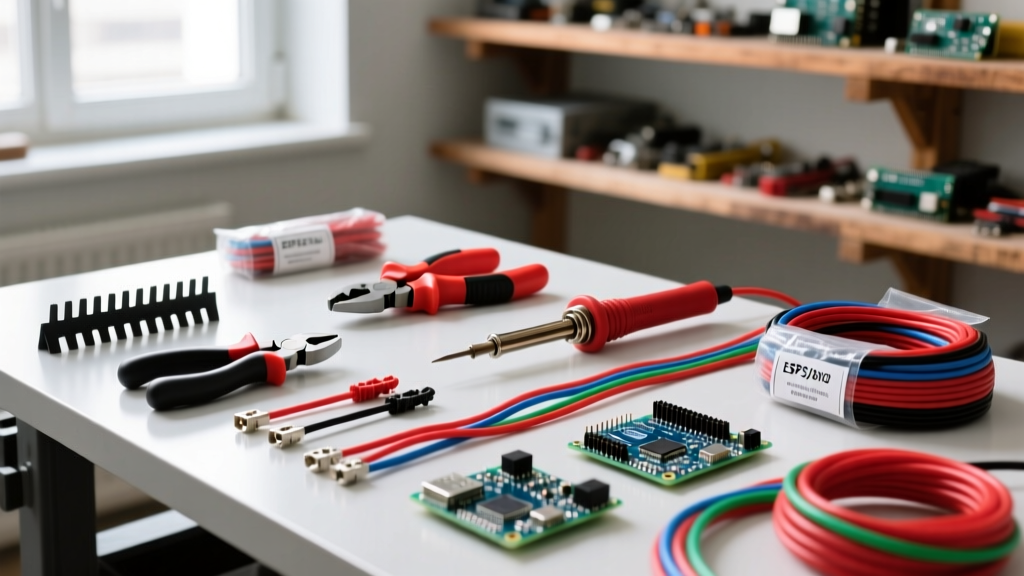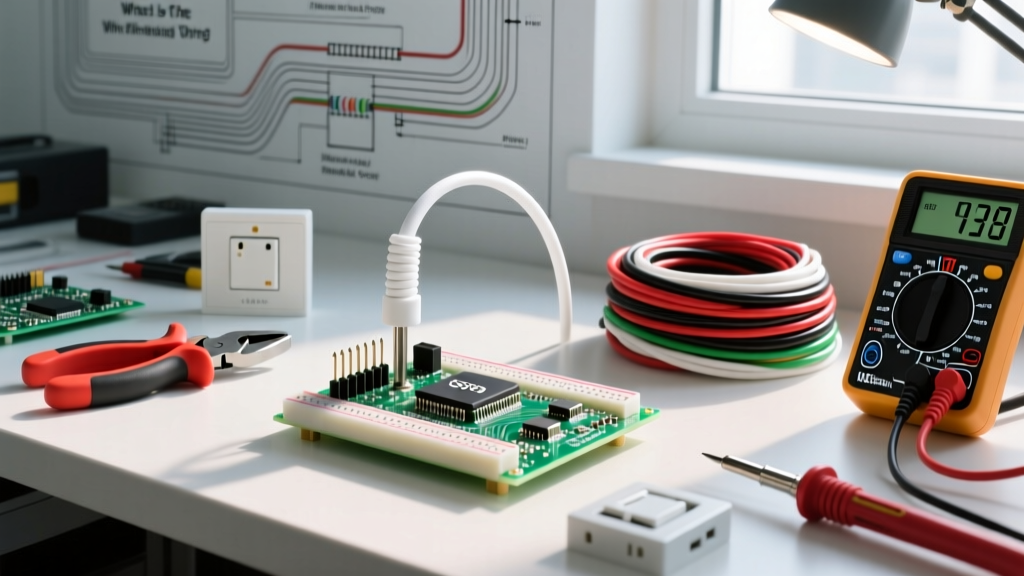

The Shift Toward Bespoke Smart Home Renovations
As we move through 2026, high-end residential renovations and commercial remodels are increasingly moving away from off-the-shelf smart switches in favor of bespoke, microcontroller-driven interfaces. Whether you are building a custom AV control room, an automated woodworking shop, or an accessibility-focused living space, integrating arduino button wiring directly into your wall infrastructure offers unmatched flexibility. However, bridging the gap between low-voltage DIY electronics and high-voltage NEC-compliant building codes requires meticulous planning during the rough-in phase. You cannot simply run jumper wires behind drywall; doing so invites fire hazards, signal degradation, and failed inspections.
NEC Compliance: Separating High and Low Voltage
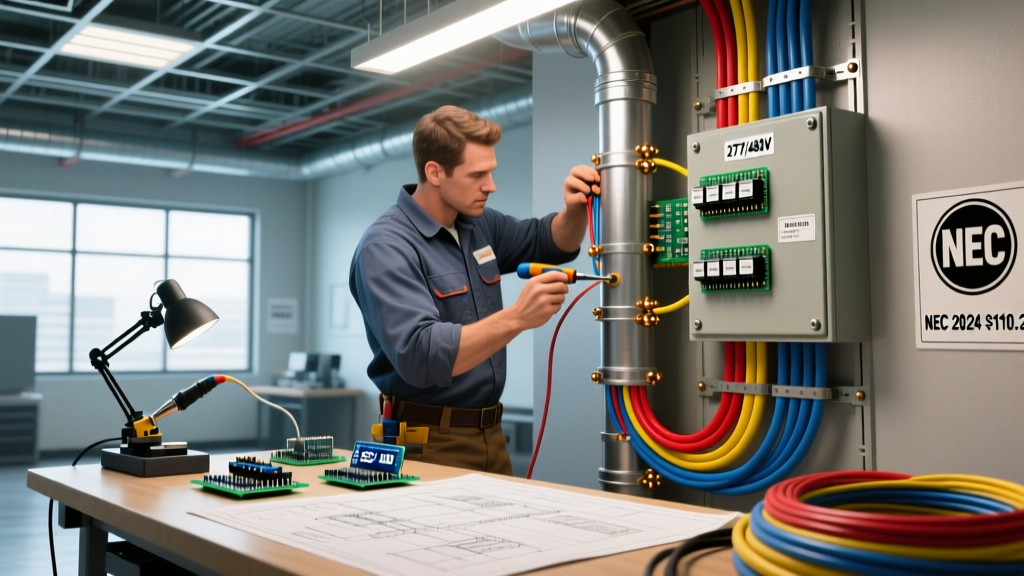
The most critical aspect of planning any in-wall microcontroller integration is adhering to the National Electrical Code (NEC). According to NFPA 70 (NEC), specifically Article 725 regarding Class 1, Class 2, and Class 3 remote-control and signaling circuits, low-voltage DC wiring must be physically separated from line-voltage AC wiring.
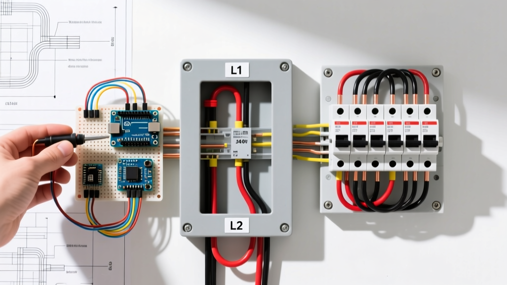
NEC Article 725.136(A) Separation Requirement: Low-voltage Class 2 and Class 3 circuit conductors must be separated from Class 1 (120V/240V) conductors by at least 2 inches, or by a continuous and firmly fixed nonconductor (physical barrier) in addition to the insulation on the wire.
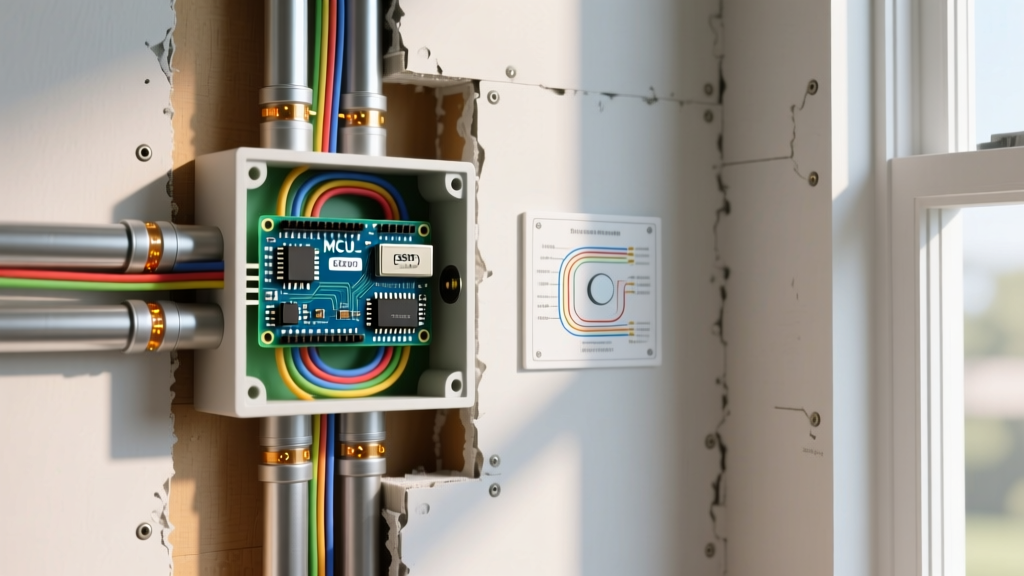
During your renovation planning, this means you must specify deep gang boxes (such as the Carlon B618R-UPC 1-gang 18 cu in box) equipped with low-voltage divider plates. If your Arduino-based node requires a local 120V AC to 5V DC step-down converter (like a Hi-Link HLK-PM01) to power the microcontroller, the AC side and the DC side must exist in separate compartments within the same electrical box, or you must use a pre-certified, UL-listed isolated power supply module.
Wire Sizing, EMI, and Voltage Drop
Standard arduino button wiring tutorials rely on 22 AWG jumper wires and internal pull-up resistors over distances of a few inches. In a home renovation, a button located on a far wall might be 40 feet away from the central microcontroller hub. Over these distances, two major issues arise: voltage drop and Electromagnetic Interference (EMI) from adjacent 12/2 or 14/2 Romex AC cables.
If you are using 3.3V logic (standard on modern ESP32 nodes), EMI can easily induce phantom voltages, causing the microcontroller to register 'ghost' button presses. To combat this, professional renovation planning dictates the use of Shielded Twisted Pair (STP) cable and, for runs exceeding 25 feet, stepping up the signaling voltage to 12V or 24V, then using an opto-isolator (like the PC817) at the microcontroller end to step the logic back down safely.
| Cable Type | AWG | Shielding | Best Renovation Use Case | Est. Cost per 100ft (2026) |
|---|---|---|---|---|
| Standard Ribbon Cable | 26 | None | Prototyping only (NEC Violation if in-wall) | $15 |
| Thermostat Wire | 18 | Unshielded | Short runs (<15ft), dry areas, 12V signaling | $28 |
| Belden 9841 (STP) | 24 | Foil + Drain | Long runs, high EMI environments, 3.3V logic | $95 |
| Plenum-Rated Cat6 | 23 | Foil/Braid | Future-proofing, PoE nodes, commercial drops | $135 |
Component Selection for In-Wall Environments
When selecting hardware for an arduino button wiring infrastructure, you must account for the harsh realities of construction environments: drywall dust, temperature fluctuations, and decades of mechanical wear.
Microcontroller Nodes
While the classic Arduino Nano is a staple for bench prototyping, it lacks native wireless capabilities and operates at 5V, which is less ideal for modern low-power signaling. For 2026 renovation standards, the ESP32-S3 (priced around $7 to $9 per module) is the superior choice. It supports WiFi 4 and Bluetooth 5 (LE), allowing it to interface with Matter-over-Thread smart home hubs without requiring physical data cables running back to a central server. Furthermore, the ESP32's capacitive touch GPIO pins allow you to wire up custom metallic faceplates as buttons, eliminating mechanical switches entirely.
Switch Hardware
Mechanical tactile switches (like the common Omron B3F series) are highly susceptible to failure when exposed to the fine particulate dust generated during drywall sanding and painting. For flush-mount wall plates in high-traffic or wet areas (like kitchens and bathrooms), specify Piezoelectric switches. According to Schurter's industrial component guidelines, piezo switches generate an electrical charge via mechanical stress on a crystal, meaning they have zero moving parts and are completely sealed against IP68-level dust and moisture intrusion. A Schurter PSE 16 piezo switch costs roughly $35 to $45, but it guarantees a lifespan of over 20 million actuations, making it a permanent fixture in your renovation.
Step-by-Step Rough-In Planning
To ensure your low-voltage infrastructure is ready before the drywall goes up, follow this rough-in sequence:
- Map the Topology: Decide between a Star topology (all button wires run back to a single central closet hub) or a Node topology (each wall switch box contains its own ESP32 and only requires power and WiFi). Node topology drastically reduces copper wire costs and conduit fill.
- Install Low-Voltage Mud Rings: Use dedicated low-voltage brackets (e.g., Arlington LV1) for the button interfaces. Do not share a standard enclosed gang box with 120V AC unless a UL-listed physical divider is installed.
- Pull and Route Cable: Pull your Belden STP or Cat6 cable, maintaining the strict 2-inch clearance from all AC Romex. If crossing an AC wire is unavoidable, do so at a strict 90-degree angle to minimize inductive coupling.
- Leave Service Loops: Leave at least 12 to 18 inches of extra cable coiled inside the wall cavity at both the switch end and the hub end. This allows for future termination repairs without opening the drywall.
- Cap and Protect: Wrap the exposed ends of your low-voltage cables in electrical tape or use push-in wire connectors to prevent drywall mud and paint from ruining the bare copper strands before termination.
Common Failure Modes and Troubleshooting
Even with meticulous planning, in-wall microcontroller circuits can fail if edge cases are ignored. Here are the most common issues encountered during post-renovation commissioning:
- Floating Pins and Ghost Presses: If the ground wire in your STP cable breaks or is improperly terminated, the microcontroller's input pin becomes 'floating.' As explained in SparkFun's guide on pull-up resistors, a floating pin acts as an antenna, picking up ambient EMI and triggering random button presses. Fix: Always use external 10kΩ pull-up resistors at the microcontroller end rather than relying solely on internal software pull-ups for long wire runs.
- Switch Bounce on Long Wires: The capacitance of a 40-foot cable can actually cause mechanical switch bounce to last longer than standard software debouncing routines expect. Fix: Increase your software debounce delay from the standard 50ms to 150ms, or add a 0.1µF ceramic capacitor in parallel with the physical button to filter out high-frequency noise.
- Power Supply Brownouts: If you are powering an ESP32 and a 5V relay module from a cheap, unbranded wall-wart hidden in a junction box, the inrush current of the relay coil will cause a voltage drop, resetting the microcontroller. Fix: Use a dedicated 5V 2A Mean Well IRM-10-5 enclosed power supply, and place a 470µF electrolytic capacitor across the 5V and GND rails near the relay coil to absorb inrush spikes.
By treating your arduino button wiring not as a temporary breadboard experiment, but as a permanent, code-compliant building system, you ensure that your custom smart-home renovation remains reliable, safe, and scalable for decades to come.