
The Anatomy of a Circuit: Defining Line and Load
In residential and commercial electrical systems, understanding the directional flow of current is not just a matter of code compliance; it is the foundation of safe circuit operation. When troubleshooting any branch circuit, the most common point of failure for DIYers and apprentice electricians alike is confusing the line and load conductors. Before diving into diagnostic procedures, we must establish precise definitions for these terms as they apply to modern electrical installations.
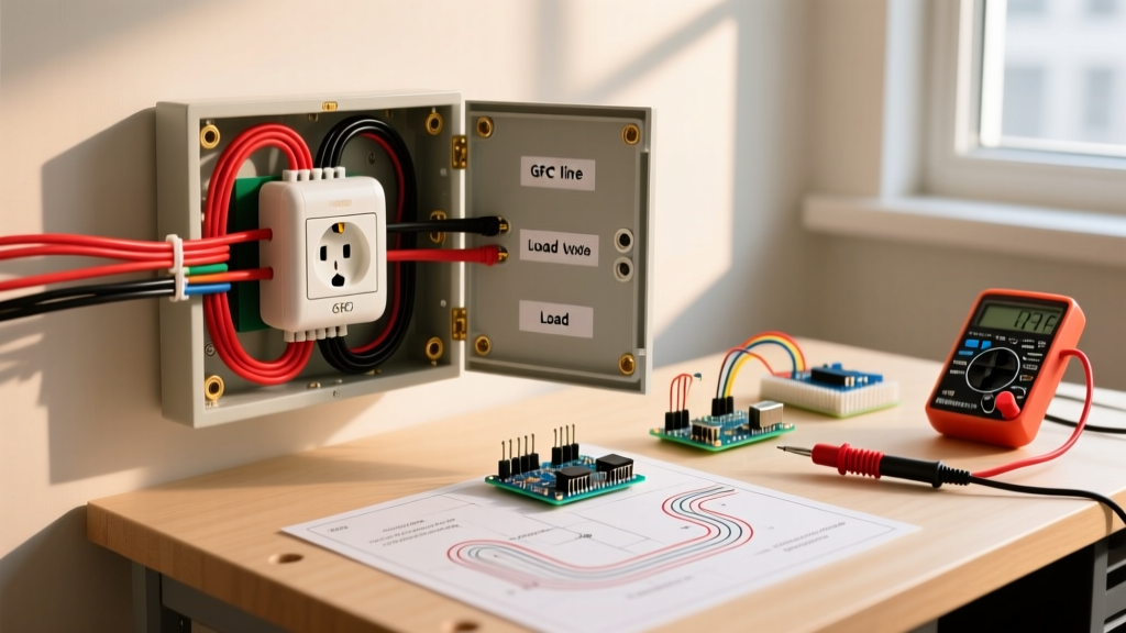
- Line (The Source): The 'line' side refers to the incoming power source. This is the wire bringing voltage directly from the main service panel, subpanel, or the upstream breaker. In a standard North American 120V circuit, this conductor carries the full nominal voltage (typically 115V to 125V) relative to ground.
- Load (The Destination): The 'load' side refers to the outgoing power. This wire carries current away from the device (switch, receptacle, or GFCI) to feed downstream devices, such as additional outlets, hardwired lighting, or the specific appliance being controlled.
While a standard duplex receptacle will function regardless of which brass screw the hot wire is attached to, modern protective and smart devices are strictly directional. Reversing these connections creates a cascade of operational failures and severe safety hazards.
Why Line vs Load Reversals Matter in 2026
The evolution of the National Electrical Code (NEC) through the 2023 and 2026 cycles has drastically expanded the requirements for Ground Fault Circuit Interrupter (GFCI) and Arc Fault Circuit Interrupter (AFCI) protection. Furthermore, the proliferation of smart home technology has introduced microprocessor-driven switches that rely on precise line/load orientation to power their internal radios and triacs.
The GFCI Reverse Line-Load Protection Standard
Prior to 2003, a GFCI receptacle wired backward (line connected to load terminals, and vice versa) would still trip and protect a user at that specific outlet, but it would fail to protect any downstream outlets. To combat this, Underwriters Laboratories (UL) updated the UL 943 standard. Today, modern GFCIs—such as the ubiquitous Leviton 07299-W or Tamper-Resistant models—feature internal reverse line-load protection. If you wire them backward, the internal mechanism physically blocks the reset button from engaging. If your GFCI refuses to reset after installation, a line/load reversal is your primary suspect.
Smart Switch and Dimmer Burnout
Smart switches like the Lutron Caseta PD-5S-DV or Leviton Decora Smart DW15S contain internal power supplies that draw a small amount of current to maintain Wi-Fi or RF connectivity. These internal circuits are designed to reference the line voltage and the neutral. If connected to the load side, the switch may attempt to draw power through the connected lighting fixture (creating a 'ghost voltage' loop). This causes flickering, failure to connect to the network, or catastrophic thermal failure of the internal switching relay.
Pro-Tip from the Field: Never trust wire colors blindly. In older homes, previous owners may have used white wires as hot switch legs, or red wires as neutrals in miswired 3-way circuits. Always verify with a meter.
Essential Diagnostic Toolkit
To safely and accurately troubleshoot electrical wiring line vs load scenarios, you must move beyond guesswork and rely on calibrated testing equipment. Do not use a simple two-prong solenoid tester (Wiggy) for this task, as it cannot measure exact voltage drops or verify neutral integrity.
- True-RMS Digital Multimeter: The Fluke 117 is the industry standard. Its non-contact voltage (NCV) feature and low-impedance (LoZ) mode are critical for identifying ghost voltages on the load side.
- Dual-Range Non-Contact Voltage Tester: The Klein Tools NCVT-3 allows you to test both standard (12-1000V) and low-voltage (12-1000V) ranges, ensuring you do not miss a backfed load wire.
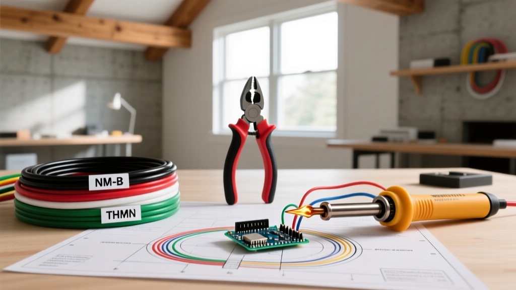
- Pigtail Testing Adapters: Wago 221-2 lever nuts and 12 AWG THHN pigtails allow you to safely isolate and test wires without them touching the metal workbox.
Step-by-Step Line and Load Isolation Procedure
When faced with an unmarked junction box containing multiple black and white wires, follow this strict isolation protocol to identify the line conductor.
- De-energize and Verify: Turn off the circuit breaker. Use your Fluke 117 to verify 0.0V between all hot wires, neutral wires, and the bare copper ground.
- Disconnect and Separate: Remove the device (switch or receptacle) from the circuit. Disconnect all hot (black/red) wires and all neutral (white) wires. Separate them so they cannot touch each other or the metal box.
- Cap the Neutrals: Temporarily group all white neutral wires together using a Wago lever nut. Group all bare ground wires together.
- Isolate the Hots: Leave the black/red wires separated and uncapped, ensuring they are safely positioned away from the grounds.
- Energize the Circuit: Turn the breaker back ON. Exercise extreme caution, as exposed conductors are now live.
- Test for Line Voltage: Set your multimeter to AC Voltage. Place the black probe on the bundled ground wires. Use the red probe to test each separated black/red wire. The single wire that reads 115V–125V is your LINE. All other wires reading 0V are LOAD wires feeding downstream devices.
- De-energize and Terminate: Turn the breaker OFF. Verify 0V again. Connect the identified LINE wire to the LINE terminal of your new device, and the remaining wires to the LOAD terminal.
Troubleshooting Matrix: Symptoms of Reversed Connections
Use the following matrix to quickly diagnose a suspected line/load reversal based on the behavior of the installed device.
| Device Type | Primary Symptom of Reversal | Secondary Symptoms | Risk Level & Code Implication |
|---|---|---|---|
| GFCI Receptacle | Reset button physically will not latch or engage. | Test button does nothing; no power to downstream outlets. | High. Violates NEC 406.4(D). Downstream protection is completely defeated. |
| AFCI Breaker | Breaker trips immediately upon energizing the circuit. | Arc fault LED indicator blinks in a specific manufacturer sequence. | High. The breaker's internal sensor reads the load signature backward, misinterpreting normal inrush current as an arc. |
| Smart Switch (Wi-Fi/Z-Wave) | Switch powers on but relay clicks repeatedly without turning on the light. | App shows device as 'offline' or 'overheating'. | Medium. Risk of internal triac burnout. Voided manufacturer warranty. |
| Standard Dimmer (e.g., Lutron Diva) | Dimmer operates normally but emits a high-pitched buzzing noise. | Connected LED bulbs flicker at low dimming levels. | Low. Primarily an operational nuisance, though it reduces dimmer lifespan due to improper heat sinking. |
| Motion Sensor Switch | Sensor fails to detect motion; light stays on permanently. | Internal relay hums continuously. | Medium. The internal logic board is backfed through the load path, bypassing the motion-detection circuitry. |
Advanced Edge Case: Multi-Wire Branch Circuits (MWBC)
The most dangerous scenario when troubleshooting line and load wires occurs in Multi-Wire Branch Circuits. An MWBC utilizes two hot wires (typically one black, one red) sharing a single white neutral wire, powered by two adjacent single-pole breakers (or one double-pole breaker) on opposite phases of the electrical panel. This provides 240V across the two hots, but 120V from either hot to the neutral.
If you are troubleshooting a 3-way switch box or a split-wired receptacle in a kitchen, you may find two distinct line sources. If you mistakenly cap the red and black wires together thinking one is a line and one is a load, you will create a dead short across 240V the moment the breaker is turned on. This will result in an immediate arc flash and destroyed breaker contacts.
How to test for an MWBC: With the circuit energized and the hot wires separated, measure the voltage between the black wire and the red wire. If you read approximately 240V, you are dealing with an MWBC. Both wires are LINE sources from different phases. They must never be tied together or treated as a line/load pair. According to OSHA electrical installation standards and the NEC, MWBCs must also feature a simultaneous disconnect mechanism (handle tie) to ensure both line sources are killed during maintenance.
Verifying Neutral Integrity on the Load Side
A common misdiagnosis in line vs load troubleshooting is blaming the hot wires when the actual failure lies in the neutral path. If you have correctly identified the line hot, connected it to the device, and the device still fails to power on, you must test the load neutral.
Using your multimeter, measure the voltage between the LINE hot and the bundled LOAD neutrals. If you read 120V, the neutral path is intact. If you read 0V, or a floating ghost voltage (e.g., 40V–60V), you have an open neutral downstream. This is frequently caused by a failed backstab connection on an upstream receptacle or a broken wire nut splice inside the wall cavity. As highlighted by the Consumer Product Safety Commission (CPSC), loose or open neutrals can cause severe voltage imbalances in multi-wire circuits, leading to appliance destruction and fire hazards.
Final Safety and Code Compliance Reminders
Troubleshooting electrical wiring line vs load configurations requires patience and strict adherence to lockout/tagout (LOTO) procedures. Never attempt to identify wires by 'tapping' them together to see which one sparks. This archaic method causes micro-pitting on conductor ends, increasing resistance and creating localized heat buildup inside the wall.
Always ensure that when terminating a new GFCI or smart device, the bare copper ground wire is securely bonded to the metal workbox (if applicable) and the device's green ground screw. For comprehensive guidelines on home electrical safety and arc-fault prevention, refer to the National Fire Protection Association (NFPA) resources. When in doubt, or if the wiring topology defies standard NEC color-coding conventions, halt the project and consult a licensed master electrician.