
The High Stakes of Trailer Brake Wiring Compliance
When it comes to towing heavy loads, electric trailer brake wiring is the central nervous system of your rig's stopping power. A frayed wire, an undersized gauge, or a misconfigured breakaway switch doesn't just risk a blown fuse—it risks catastrophic failure on a mountain downgrade. From a regulatory standpoint, commercial and heavy-duty recreational trailers are subject to stringent federal and state inspections. Failing a Department of Transportation (DOT) or Commercial Vehicle Safety Alliance (CVSA) roadside inspection due to electrical non-compliance results in immediate out-of-service (OOS) orders, hefty fines, and severe liability in the event of an accident.
This guide provides a deep-dive, inspector-level breakdown of electric trailer brake wiring compliance, covering SAE standards, federal mandates, and the exact failure modes that trigger roadside violations.
SAE J286 Compliance: The 7-Way RV Blade Connector
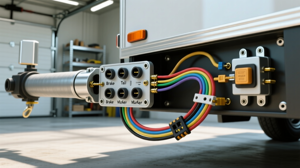
The 7-way RV blade connector is the undisputed standard for electric trailer brakes in North America. However, simply plugging it in does not guarantee compliance. The Society of Automotive Engineers (SAE) standard J286 dictates the exact pinout, wire color coding, and functional requirements for these connectors. During a Level I or Level II DOT inspection, officers will verify that your physical wiring matches the mandated SAE J286 pinout.
Standard 7-Way Pinout & Minimum Wire Gauge Requirements
| Pin / Clock Position | Function | Standard Wire Color | Minimum AWG (Compliance) |
|---|---|---|---|
| Pin 1 (9 o'clock) | Left Turn / Stop | Yellow | 12 AWG |
| Pin 2 (10 o'clock) | Reverse Lights / Aux | Black | 16 AWG |
| Pin 3 (7 o'clock) | Ground (White) | White | 10 AWG |
| Pin 4 (3 o'clock) | Right Turn / Stop | Green | 12 AWG |
| Pin 5 (1 o'clock) | Electric Brakes | Blue | 10 AWG |
| Pin 6 (11 o'clock) | Tail / Marker Lights | Brown | 16 AWG |
| Pin 7 (5 o'clock) | 12V Aux / Breakaway | Red or Black | 12 AWG |
Inspector Note: While 12 AWG is often used for the brake circuit (Pin 5) on light-duty single-axle trailers, 10 AWG is the strict compliance standard for multi-axle trailers and commercial rigs to prevent voltage drop under high-amperage braking events.
Wire Insulation Standards: Why THHN and PVC Fail Inspections
One of the most common reasons electric trailer brake wiring fails a CVSA inspection is the use of inappropriate wire insulation. Many DIY builders and budget manufacturers use standard PVC-jacketed wire (like THHN or standard automotive primary wire) for exterior trailer routing. This is a direct violation of SAE J1128 standards for automotive cable.
The SAE J1128 Mandate: GXL and TXL Wire
For exterior and undercarriage routing, wiring must be rated for high temperatures, chemical exposure (road salt, diesel, hydraulic fluid), and physical abrasion. SAE J1128 specifies the use of Cross-Linked Polyethylene (XLPE) insulated wires, specifically:
- GXL (General Cross-Linked): The industry standard for trailer brake wiring. It features a thicker insulation wall, offering superior abrasion resistance against road debris.
- TXL (Thin-Wall Cross-Linked): Offers the same chemical and thermal resistance as GXL but with a thinner jacket, saving weight and allowing for tighter bending radii in conduit.
As of 2026, high-quality 10 AWG GXL wire costs approximately $0.95 to $1.30 per foot. Using standard PVC wire, which degrades under UV exposure and becomes brittle below freezing, will result in cracked jackets and exposed copper—an instant out-of-service violation during a DOT tread and wiring check.
Breakaway Switch Wiring: 49 CFR § 393.43 Compliance
Federal law mandates that any trailer with a Gross Vehicle Weight Rating (GVWR) over 3,000 lbs must be equipped with an automatic emergency breakaway braking system. According to 49 CFR § 393.43, the breakaway system must be capable of holding the trailer brakes in the applied position for at least 15 minutes after a complete severance from the tow vehicle.
The Most Common Wiring Violation: Series vs. Parallel
The most frequent electrical failure cited by DOT inspectors is wiring the breakaway switch in series with the brake controller's output wire. This is illegal and highly dangerous. If the breakaway switch is wired to draw power from the tow vehicle's 7-way Pin 5 (the brake controller feed), a complete severance of the 7-way plug will cut power to the breakaway switch, rendering it useless.
Compliant Breakaway Wiring Protocol
- Independent Power Source: The breakaway switch (e.g., Tekonsha 2005-P or Curt 5242) must be wired directly to a dedicated, onboard 12V trailer battery.
- Battery Sizing: The onboard battery must be a minimum of 5Ah (Sealed Lead Acid or LiFePO4) to sustain the 10-15 amp draw of the brake magnets for the federally mandated 15 minutes.
- Switch Placement: The switch must be mounted to the trailer frame, with the pull-pin lanyard attached to the tow vehicle's frame or bumper—never to the safety chains or the hitch ball.
CVSA Out-of-Service Criterion: If an inspector pulls the breakaway pin and the trailer brakes do not immediately lock and hold, or if the system draws power from the tow vehicle rather than an independent onboard battery, the rig is placed out of service immediately. Read more on inspection criteria via the CVSA North American Standard Inspections portal.
The Grounding Fallacy: Avoiding the 'White Wire' Shortcut
In electric trailer brake wiring, the ground circuit (Pin 3, White Wire) carries the return current for the entire trailer's electrical system, including the high-amperage brake magnets. A common, non-compliant shortcut is relying on the physical connection between the hitch ball and the trailer coupler to serve as the ground path, while only running a thin 16 AWG white wire to the trailer's running lights.
Why Chassis Grounding Fails
Hitch balls and couplers are subject to rust, paint overspray, grease, and dynamic bouncing. Relying on the hitch for a ground path causes severe voltage drops, leading to dim lights and, more critically, weak brake actuation. Compliance requires a dedicated 10 AWG white ground wire routed from the 7-way plug directly to the trailer's main grounding bus bar, which is then bonded to the trailer frame using a star washer and bare metal contact. Voltage drop testing across the ground circuit under a 10-amp load should read no more than 0.3V.
Connection Methods: Crimping vs. Soldering in High-Vibration Zones
While soldering is considered best practice in static electronics, it is heavily frowned upon—and often failed—in high-vibration automotive and trailer applications. Solder wicks into the wire strands, creating a rigid point that transitions to flexible wire. Under the constant harmonic vibration of a trailer axle, this rigid-to-flexible transition point acts as a stress riser, leading to copper fatigue and internal wire breakage.
The Compliant Connection Standard
Inspectors look for adhesive-lined heat shrink crimps. The correct procedure involves using a ratcheting crimping tool (such as the IWISS IWS-10SN or Titan 11210) to compress a copper barrel crimp, followed by heating a dual-wall, polyolefin heat shrink tube. The inner adhesive layer melts and seals the connection against moisture intrusion, preventing 'green rot' (copper oxidation), while the crimp maintains mechanical flexibility.
Pre-Trip DOT Inspection Checklist for Trailer Wiring
To ensure your electric trailer brake wiring passes a FMCSA Part 393 compliance audit, run through this CVSA-aligned checklist before every haul:
- Drip Loops: Verify the 7-way pigtail has a sufficient drip loop before entering the trailer frame to prevent water from wicking into the connector.
- Abrasion Protection: All wiring routed along the exterior frame must be secured every 18 inches and protected by split loom or nylon braided sleeving where it passes through metal crossmembers.
- Clearance: Wiring must maintain a minimum 6-inch clearance from exhaust components and moving suspension parts.
- Pin Tension: Check the 7-way plug pins. If the pins are spread or loose, they will cause arcing and voltage drop. Replace molded pigtails (like the Bargman 54005-044) if pin tension is lost.
- Magnet Wiring: Inspect the final 12-inch run to the brake backing plate. This area sees the most debris impact. Ensure the heat shrink seals at the magnet wire entry point are fully intact and not cracked.
Frequently Asked Questions (FAQ)
Can I use a 4-way flat to 7-way adapter for electric brakes?
No. A 4-way flat connector only supports lighting (ground, tail, left turn, right turn). It lacks the dedicated 10 AWG blue wire required for the brake controller output and the 12V auxiliary feed for the breakaway battery. Using an adapter for electric brakes is a severe safety hazard and an automatic DOT violation.
What is the acceptable voltage drop for the brake circuit?
Under a simulated 10-amp load (or with the brake controller manually overridden to maximum output), the voltage drop from the controller's output terminal to the brake magnet wire on the furthest axle should not exceed 0.5V. If your tow vehicle outputs 12.2V and the magnet receives 11.4V, you have a 0.8V drop, indicating undersized wire or corroded connections that require immediate remediation.
Do I need a circuit breaker on the trailer brake wire?
Yes. SAE and NEC guidelines recommend a 30-amp or 40-amp auto-reset thermal circuit breaker (such as the Bussmann CB185) installed within 18 inches of the trailer's main power junction block on the blue brake feed wire. This protects the trailer wiring from melting in the event of a shorted brake magnet coil.