
The Unique Challenges of Electric Furnace Thermostat Wiring
Unlike gas furnaces that rely on a single gas valve and a simple W terminal connection, electric furnaces utilize high-voltage resistance heating elements controlled by low-voltage sequencers. This fundamental difference means that thermostat wiring for electric furnace setups often requires multi-stage configurations (W1, W2, W3) or specialized auxiliary heat logic. When your system fails to produce heat, blows cold air, or causes your smart thermostat to endlessly click, the fault usually lies in the 24VAC control circuit, the sequencer coils, or an undersized wire gauge.
In this comprehensive 2026 troubleshooting guide, we will bypass generic HVAC advice and dive deep into the exact multimeter readings, terminal mappings, and failure modes specific to electric resistance heating systems.
⚠️ CRITICAL SAFETY WARNING: Electric furnaces operate on 240VAC for the heating elements and 120VAC for the blower motor and control board. Before touching any thermostat wires or opening the air handler panel, turn off BOTH the dedicated 240V double-pole breaker and the 120V control circuit breaker. Verify zero voltage with a non-contact voltage tester (NCVT) and a digital multimeter.
Terminal Mapping: Electric Furnace vs. Heat Pump
One of the most common DIY errors is treating an electric furnace like a heat pump. Heat pumps require O/B terminals for the reversing valve. Straight electric furnaces do not. Connecting a wire to the O/B terminal on an electric furnace can cause a short circuit, immediately blowing the 3A ATC fuse on your air handler's control board.
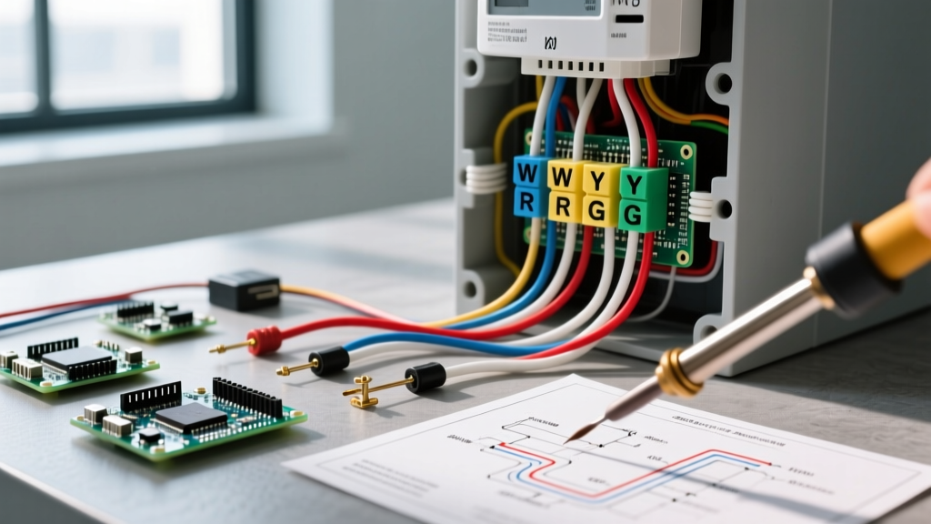
| Terminal | Function in Electric Furnace | Expected Voltage (Calling) | Target Component |
|---|---|---|---|
| R / Rc / Rh | 24VAC Power Supply | 24VAC (Constant) | Control Board Transformer |
| C | 24VAC Common Return | 0VAC (Reference) | Control Board Transformer |
| W1 | Stage 1 Heat Request | 24VAC | Sequencer 1 Coil / Fan Relay |
| W2 | Stage 2 Heat Request | 24VAC | Sequencer 2 Coil |
| E / Aux | Emergency Heat Bypass | 24VAC | All Sequencers / Heat Strips |
| G | Blower Fan Control | 24VAC | Fan Relay / Control Board |
Step-by-Step Troubleshooting Scenarios
Scenario 1: System Blows Cold Air in 'Heat' Mode
If your thermostat calls for heat, the blower engages, but the air remains room temperature, the heating elements (heat strips) are not energizing. This is a classic failure in thermostat wiring for electric furnace circuits.
- Check the 3A Control Board Fuse: Open the air handler panel and locate the printed circuit board. Look for an automotive-style 3A blade fuse (often purple). If it is blown, a short occurred. Do not just replace it. Find the short first.
- Test Thermostat Output: Set your multimeter to VAC. With the thermostat calling for heat, measure between the R and W1 terminals at the thermostat baseplate. You should read 24VAC (+/- 2V). If you read 0V, the thermostat internal relay is faulty.
- Test Sequencer Coil Resistance: If the thermostat is sending 24VAC but the sequencer isn't pulling in, turn off the power. Disconnect the W1 wire at the sequencer coil. Set your multimeter to Ohms (Ω). A healthy White-Rodgers or similar sequencer coil should read between 20 and 50 ohms. If it reads 'OL' (Open Line), the coil is burned out and the sequencer must be replaced.
Scenario 2: Smart Thermostat Clicking Endlessly (No Heat)
Modern smart thermostats like the Ecobee SmartThermostat Premium or the Nest Learning Thermostat (4th Gen) require constant power to run their Wi-Fi radios and displays. If your electric furnace lacks a dedicated C-wire (Common), the smart thermostat will attempt to 'steal' power by backfeeding a small current through the W1 or Y circuits.
- The Failure Mode: Electric furnace sequencer coils have very low resistance. The power-stealing current is enough to cause the sequencer to 'chatter' (click rapidly) or partially engage, but not enough to close the high-voltage 240V contacts. This results in no heat and eventually burns out the sequencer coil.
- The Fix: Run a new 18/5 or 18/8 AWG thermostat cable from the air handler to the thermostat. Connect the unused wire to the C terminal on the control board and the C terminal on the thermostat. According to the EPA ENERGY STAR Smart Thermostat Guidelines, a dedicated C-wire is strongly recommended to prevent HVAC equipment damage and ensure optimal energy-saving algorithms function correctly.
Scenario 3: Blower Fan Runs Continuously, No Heat Call
If the fan never shuts off, even when the thermostat is set to 'Off', you likely have a short between the R and G wires, or a failed fan limit switch.
- Isolate the Thermostat: Remove the thermostat from the baseplate. If the fan stops, the short is inside the thermostat head or the baseplate wiring is pinched.
- Check the Wire Run: If the fan continues to run with the thermostat removed, the short is in the wall cavity or attic. Look for areas where the 18 AWG thermostat wire was stapled too tightly, crushing the insulation and allowing the R and G copper strands to touch.
- Inspect the Fan Limit Switch: Older electric furnaces use a bimetallic fan limit switch. If the contacts weld shut due to age or arcing, the fan will run 24/7. Test for continuity across the fan switch terminals; replace if closed while the unit is cold.
Wire Gauge and Voltage Drop: The Hidden Culprit
Many DIYers and even some HVAC installers use whatever wire is left in the truck, often opting for 20 AWG or 22 AWG security wire to save money. This is a severe violation of best practices and can lead to intermittent heating failures.
The U.S. Department of Energy and standard electrical codes emphasize proper conductor sizing for control circuits. For 24VAC Class 2 circuits, 18 AWG is the minimum standard. If your thermostat is located more than 50 feet from the air handler, the resistance of 18 AWG wire can cause a voltage drop. Sequencers typically require a minimum of 18VAC to reliably pull the magnetic contacts closed. If voltage drops to 16VAC at the sequencer due to undersized wire, the sequencer will hum, overheat, and fail to engage the heat strips.
Calculating Your Voltage Drop
Use this formula to ensure your wiring is adequate:
Voltage Drop = (2 x Length x Current x Resistance per 1000ft) / 1000
- 18 AWG Copper Resistance: ~6.385 ohms per 1000 ft
- Typical Sequencer Coil Draw: ~0.1 Amps (100mA)
- Rule of Thumb: For runs under 75 feet, standard 18/5 solid copper wire is perfectly adequate. For runs exceeding 75 feet, upgrade to 16 AWG thermostat wire to eliminate voltage drop and ensure your electric furnace sequencers receive a crisp, full 24VAC signal.
Final Verification Checklist
Before buttoning up your air handler and declaring the job complete, run through this final verification matrix to ensure your thermostat wiring for electric furnace is safe and code-compliant:
- [ ] Wire Stripping: Exactly 3/8 inch of insulation removed. No exposed copper outside the terminal block.
- [ ] Strand Check: No loose copper 'whiskers' sticking out of the R, W, or C terminals that could arc to adjacent terminals.
- [ ] Thermostat Configuration: In the smart thermostat's advanced menu, ensure the auxiliary heat type is set to 'Electric' (not Gas) and the staging is matched to your physical heat strips (e.g., 10kW or 15kW).
- [ ] Delta T Test: Turn the system to Heat. Measure the return air temperature and the supply air temperature at the closest register. For a standard 15kW electric furnace moving 1200 CFM, you should see a temperature rise (Delta T) of approximately 40°F to 45°F. If the rise is only 15°F, one or more of your sequencers or heat strips are still failing to engage.
By understanding the specific sequencer logic, respecting the 24VAC control boundaries, and ensuring proper wire gauge, you can reliably troubleshoot and repair almost any electric furnace thermostat wiring issue without relying on expensive emergency service calls.