
Mastering the 3-Way Switch Circuit Architecture
Controlling a single light fixture from two separate locations—such as the top and bottom of a staircase or dual entrances to a kitchen—is a fundamental home electrical upgrade. However, consulting a precise diagram for wiring a 3 way switch is critical before stripping your first wire. Unlike a standard single-pole switch that simply breaks a hot wire, a 3-way circuit relies on a continuous loop of 'traveler' wires to route power based on the physical toggle position of both switches.
In this 2026 home project guide, we break down the exact anatomy, National Electrical Code (NEC) requirements, and step-by-step installation procedures for a standard 3-way circuit. According to the Occupational Safety and Health Administration (OSHA), electrical work consistently ranks among the top hazards for DIYers; proper preparation and adherence to code are non-negotiable.
The Four Critical Terminals
A standard 3-way switch (such as the widely used Leviton Decora 5603-2W) features four connection points:
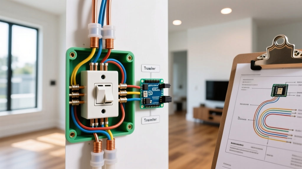
- Common Terminal (Dark Brass/Black Screw): The pivot point. On the first switch, it connects to the incoming hot (line). On the second switch, it connects to the outgoing load (light fixture).
- Traveler Terminals (Two Light Brass Screws): These carry the alternating current between the two switches. The physical position of the toggles determines which traveler is active.
- Ground Terminal (Green Screw): Connects to the bare copper or green insulated equipment grounding conductor.
Essential Tools and Material Costs (2026 Pricing)
Before beginning, ensure you have the correct materials. Using 14 AWG wire on a 20-amp breaker is a severe fire hazard and an immediate NEC violation. Always match your wire gauge to your circuit breaker.
| Item | Specification / Model | Estimated Cost (2026) |
|---|---|---|
| 3-Way Switch | Leviton Decora 5603-2W (15A/120V) | $3.50 - $5.00 |
| Smart 3-Way Dimmer | Lutron Maestro MACL-LFQH | $65.00 - $85.00 |
| Traveler Cable | Southwire 14/3 NM-B (Romex) - 25ft | $18.00 - $22.00 |
| Wire Strippers | Klein Tools 11055 (14-16 AWG) | $28.00 - $32.00 |
| Non-Contact Voltage Tester | Fluke 1AC-II VoltAlert | $35.00 - $40.00 |
| Push-In Wire Connectors | WAGO 221 Series (3-Port) | $0.60 / each |
Decoding the Diagram for Wiring a 3 Way Switch
There are two primary topologies for a 3-way circuit. The most common in residential construction is Scenario A: Power Source at the First Switch. We will detail this layout step-by-step.
Scenario A: Power Enters at Switch 1
In this layout, the main hot and neutral from the breaker panel enter the first switch box. A 14/3 cable runs from Switch 1 to Switch 2, and a 14/2 cable runs from Switch 2 to the light fixture.
- Kill the Power & Verify: Turn off the 15A or 20A breaker. Test all wires in both boxes with your Fluke 1AC-II tester. Follow OSHA's lockout/tagout guidelines by placing a piece of tape over the breaker to prevent accidental re-engagement.
- Wire Switch 1 (Line Side):
- Connect the incoming bare copper ground to the green ground screw.
- Bundle the incoming white neutral with the white neutral of the 14/3 traveler cable using a WAGO 221 connector. Do not attach neutrals to a standard 3-way switch.
- Connect the incoming black hot wire to the Common (dark) screw on Switch 1.
- Connect the red and black wires of the 14/3 traveler cable to the two Traveler (light brass) screws.
- Wire Switch 2 (Load Side):
- Connect the bare copper ground to the green screw.
- Bundle the white neutral from the 14/3 cable with the white neutral of the 14/2 cable going to the light.
- Connect the black wire of the 14/2 cable (going to the light) to the Common (dark) screw on Switch 2.
- Connect the red and black wires from the 14/3 traveler cable to the two Traveler screws.
- At the Light Fixture: Connect the black load wire to the fixture's hot terminal, the white neutral to the fixture's neutral, and the bare copper to the fixture ground.
Scenario B: Power Enters at the Light Fixture
When power hits the ceiling box first, the diagram for wiring a 3 way switch changes slightly. You must run a 14/2 cable from the light to Switch 1, and a 14/3 from Switch 1 to Switch 2. Crucial NEC Rule: The white wire in the 14/2 cable dropping to Switch 1 will act as your constant hot feed. Per NEC Article 200.7(C)(2), you must re-identify this white wire with black electrical tape or heat shrink at both ends to indicate it is being used as an ungrounded (hot) conductor, not a neutral.
Crucial NEC Code Requirements & Box Fill Calculations
Ignoring box fill calculations leads to cramped boxes, damaged wire insulation, and failed inspections. The National Fire Protection Association (NFPA) outlines these rules in NEC Article 314.16.
Pro-Tip for 2026 Smart Home Upgrades: Smart 3-way switches (like the Lutron Maestro) have deep bodies and require extra wire bending space. Always upgrade standard 14-cubic-inch boxes to 22-cubic-inch 'deep' single-gang boxes when performing a 3-way retrofit.
Box Fill Math for Switch 1 (14 AWG Circuit)
For 14 AWG wire, the NEC assigns a volume allowance of 2.0 cubic inches per conductor.
- Hot and Neutral Wires: 3 conductors entering/leaving = 6.0 cu in.
- Ground Wires: All grounds count as a single volume allowance = 2.0 cu in.
- Switch Device: Counts as two volume allowances (2 x 2.0) = 4.0 cu in.
- Cable Clamps: Internal clamps count as one allowance = 2.0 cu in.
- Total Required Volume: 14.0 cubic inches. A standard 18 cu in. box is legally sufficient, but a 22 cu in. deep box is highly recommended for ease of installation.
Advanced Troubleshooting: Edge Cases & Failures
Even with a perfect diagram for wiring a 3 way switch, real-world variables can cause frustrating failures. Here is how to diagnose the most common edge cases.
Failure Mode 1: Switch A Only Works if Switch B is 'ON'
The Symptom: You can turn the light on and off from the hallway, but the bedroom switch does nothing unless the hallway switch is already flipped up.
The Diagnosis: The 'Common' terminal on the bedroom switch is miswired. Instead of the load wire going to the dark screw, a traveler wire was placed on the dark screw, and the load wire was placed on a brass traveler screw. The circuit only completes when the other switch aligns power to that specific traveler.
Failure Mode 2: LED 'Ghosting' or Flickering
The Symptom: You installed a smart 3-way dimmer, and the LED bulbs glow faintly when turned off, or they strobe intermittently.
The Diagnosis: Smart switches require a tiny amount of standby current to power their internal Wi-Fi radios or LED indicators. If your 3-way circuit lacks a neutral wire connection at the switch (common in older pre-2011 homes), the switch leaks this micro-current through the traveler wires and the light fixture. According to EPA ENERGY STAR guidelines, modern LEDs are highly sensitive to micro-currents. The Fix: Install a bypass capacitor (like the Lutron LUT-MLC) directly across the hot and neutral wires at the light fixture to absorb the leaked current.
Failure Mode 3: Phantom Voltage on Digital Multimeters
The Symptom: When testing the traveler wires with a high-impedance digital multimeter, you read 40V-70V on a traveler that should be 'dead'.
The Diagnosis: This is capacitive coupling (induced voltage). The energized traveler wire running parallel to the dead traveler wire inside the 14/3 Romex jacket induces a harmless 'phantom' voltage. Use a low-impedance voltage tester (LoZ) or a simple solenoid tester (Wiggy) to confirm the wire is actually dead before touching it.
Frequently Asked Questions
Can I use two single-pole switches instead of 3-way switches?
No. Single-pole switches only have two terminals and cannot route alternating current paths. Attempting to wire two single-pole switches to control one light will result in a dead short, tripping the breaker instantly and creating a severe arc flash hazard.
Does it matter which traveler wire goes to which brass screw?
Electrically, no. The traveler terminals are interchangeable on a standard mechanical 3-way switch. Swapping the red and black traveler wires will simply invert the physical toggle positions (e.g., both switches must be 'up' instead of one 'up' and one 'down' to turn the light on). However, for consistency and future troubleshooting, it is best practice to keep the red wire on the top brass screw and the black traveler on the bottom brass screw at both locations.
What if my home only has 14/2 wire between the switches?
You cannot wire a traditional 3-way circuit with only 14/2 (which lacks the red traveler wire). You must either pull a new 14/3 cable through the walls, or utilize a wireless smart switch system (like the Lutron Caseta Pico remote setup) where the secondary switch is battery-operated and communicates via RF signals, eliminating the need for physical traveler wires entirely.